TEL:+86 132 6656 7067


Telecom access networks rely on compact optical transceivers to connect aggregation switches, access routers, base station equipment, fiber distribution nodes and metropolitan transport infrastructure. SFP and SFP+ modules provide two widely deployed interface classes for these links, covering 1G and 10G Ethernet applications across different fiber types and transmission distances.
SFP modules remain common in established Gigabit Ethernet access infrastructure, while SFP+ interfaces provide higher-capacity connections for bandwidth-intensive access aggregation, mobile backhaul and enterprise service delivery. Selecting the correct module requires matching the host interface, optical reach, wavelength, fiber plant and link budget.
1. SFP and SFP+ Interfaces in Telecom Infrastructure
SFP and SFP+ are compact pluggable transceiver form factors used in network equipment with removable optical interfaces. Their physical dimensions are similar, allowing many SFP+ host ports to support lower-rate SFP modules when the equipment manufacturer enables the corresponding operating mode. This does not mean that every SFP and SFP+ combination is automatically interchangeable.
| Characteristic | SFP | SFP+ |
|---|---|---|
| Common Ethernet rate | 1GbE | 10GbE |
| Typical host interface | Gigabit serial interface | 10G serial interface |
| Common applications | Access switches, Gigabit uplinks, legacy aggregation | 10G aggregation, mobile backhaul, high-capacity uplinks |
| Optical media | Single-mode and multimode fiber | Single-mode and multimode fiber |
| Common connectors | LC duplex, depending on module design | LC duplex, with other interfaces available for specialized designs |
| Typical monitoring | DDM/DOM on supported models | DDM/DOM on supported models |
The key difference is the supported signaling rate and host equipment configuration rather than the external module dimensions. A 1G SFP cannot deliver a 10GbE connection simply because it is inserted into an SFP+ port. Port configuration, transceiver coding, supported data rates and firmware compatibility must all be checked.
2. Optical Specifications and Transmission Options
Telecom access links vary considerably in distance and optical conditions. Short connections inside a central office or equipment room may use multimode fiber, while feeder, distribution and inter-site links generally use single-mode fiber. The module wavelength and optical interface must match the installed fiber plant.
| Module Category | Typical Wavelength | Fiber Type | Typical Reach | Common Application |
|---|---|---|---|---|
| 1G SFP SX | 850nm | Multimode | Up to 550m, depending on fiber grade | Equipment-room and campus links |
| 1G SFP LX | 1310nm | Single-mode | Up to 10km | Access and distribution links |
| 1G SFP extended reach | 1550nm or other specified wavelengths | Single-mode | 40km or longer, depending on design | Longer access and aggregation links |
| 10G SFP+ SR | 850nm | Multimode | Typically 300m on OM3 or 400m on OM4 | Short-range 10G connections |
| 10G SFP+ LR | 1310nm | Single-mode | Up to 10km | Access aggregation and metro access |
| 10G SFP+ ER | 1550nm | Single-mode | Up to 40km | Extended-reach transport links |
These are representative interface categories, not universal guarantees for every module. Actual reach depends on transmitter output power, receiver sensitivity, dispersion, connector loss, fiber attenuation, splice quality and the applicable optical specification. Extended-reach modules may also require additional dispersion or optical power-budget considerations.
3. SFP Modules in Gigabit Telecom Access Networks
Gigabit SFP transceivers are widely used where 1GbE remains sufficient for customer access, equipment connectivity or legacy network infrastructure. Their compact size and range of optical options make them suitable for distributed access equipment where copper cabling would introduce distance limitations or additional maintenance requirements.
Common deployment scenarios include:
Fiber access switches: Optical uplinks connect remote access switches to aggregation equipment in a central office or regional node.
Enterprise and business access: Gigabit fiber links provide connectivity for office buildings, commercial sites and managed network services.
Wireless access infrastructure: SFP interfaces connect selected radio access and transport devices where a 1GbE link is sufficient.
Remote network cabinets: Compact modules support fiber connectivity in distributed cabinets and outdoor access installations, subject to equipment environmental ratings.
Legacy Ethernet aggregation: SFP ports extend the service life of installed Gigabit network equipment.
For these applications, 1000BASE-SX and 1000BASE-LX are common interface choices. SX is intended for multimode fiber over relatively short distances, whereas LX is commonly deployed over single-mode fiber for longer access connections.
4. SFP+ Modules for 10G Access Aggregation
As broadband service adoption, enterprise traffic and mobile network capacity increase, 1GbE uplinks can become a constraint between access nodes and aggregation layers. SFP+ provides a 10GbE interface in a compact pluggable form factor, enabling higher-capacity links without requiring a larger optical module footprint.
10G SFP+ LR modules are frequently selected for single-mode fiber connections between access switches, aggregation routers and metro Ethernet equipment. SR modules are more suitable for short-reach connections within equipment rooms or data center environments using compatible multimode fiber.
Extended-reach SFP+ options can support longer point-to-point links. However, a nominal reach rating alone is not sufficient for network design. The optical power budget, chromatic dispersion tolerance, receiver overload limit and link engineering margin must be evaluated against the actual route.
5. Deployment in FTTx and PON Access Architectures
SFP and SFP+ modules can be used in Ethernet uplinks and transport connections associated with FTTx infrastructure. In a typical access architecture, an OLT connects to an aggregation network, while passive optical splitters distribute PON signals toward ONUs or ONTs at customer locations.
Standard Ethernet SFP or SFP+ modules are not interchangeable with dedicated GPON, XG-PON or XGS-PON optical interfaces. PON systems use specific downstream and upstream wavelengths, optical power classes, burst-mode receiver requirements and protocol functions. The optical interface must therefore be designed for the relevant PON standard and OLT platform.
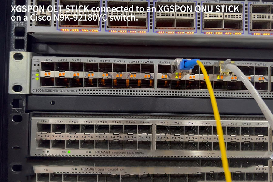
Standard SFP and SFP+ transceivers are more commonly used for Ethernet handoffs, switch uplinks and aggregation links surrounding the PON access system. Dedicated PON optical modules, including compatible OLT SFP or SFP+ stick solutions where supported, must meet the relevant PON specifications and host requirements.
| Network Segment | Typical Optical Interface | Primary Function |
|---|---|---|
| OLT to aggregation switch | Ethernet SFP or SFP+ | Uplink traffic from the access network |
| OLT to passive splitter | Dedicated GPON, XG-PON or XGS-PON optics | PON downstream and upstream transmission |
| Splitter to ONU/ONT | Dedicated PON optical interface | Subscriber-side optical access |
| Ethernet access node to metro network | SFP or SFP+ Ethernet optics | Service aggregation and transport |
6. Mobile Backhaul and Distributed Access Connections
Mobile networks require reliable transport between radio sites, distributed baseband equipment and aggregation nodes. SFP and SFP+ transceivers support different capacity levels within these transport paths, depending on the radio architecture, number of sectors, traffic profile and network synchronization requirements.
Gigabit SFP interfaces may remain suitable for selected legacy or lower-capacity connections. SFP+ interfaces provide 10GbE connectivity for higher-capacity radio access and aggregation links. Single-mode LR optics are useful where fiber routes extend between outdoor sites and aggregation facilities, while short-reach modules can connect equipment within the same facility.
Mobile transport design also involves more than raw Ethernet bandwidth. Timing and synchronization requirements, including SyncE and IEEE 1588 Precision Time Protocol where applicable, must be supported by the complete network equipment and configured transport path. The optical transceiver itself does not independently guarantee timing performance.
7. Optical Power Budget and Link Reliability
A stable access link requires sufficient optical power at the receiver while avoiding receiver overload. The optical power budget is calculated from the transmitter's minimum output power and the receiver's sensitivity, with additional consideration for system penalties and engineering margin.
A simplified link budget is:
Available Optical Power Budget (dB) = Minimum Transmitter Output Power (dBm) − Receiver Sensitivity (dBm)
The route loss must remain within the available budget. Fiber attenuation, connector insertion loss, splice loss, patch panels and other passive components all contribute to the total link attenuation.
| Link Parameter | Engineering Consideration |
|---|---|
| Tx optical power | Confirm minimum and maximum transmitter output levels. |
| Rx sensitivity | Check the minimum received optical power required for the specified BER. |
| Receiver overload | Ensure the received signal does not exceed the module's maximum input level. |
| Fiber attenuation | Use the correct wavelength-specific attenuation for the installed fiber. |
| Connector and splice loss | Include all optical connection points along the route. |
| Engineering margin | Reserve margin for aging, maintenance and environmental variation. |
A link may fail even when its calculated power budget appears adequate. Dirty connectors, excessive reflection, fiber bending, wavelength mismatch, faulty patch cords and poor splicing can cause unstable optical performance. For longer links, chromatic dispersion and other transmission impairments may also become relevant.
8. DDM Monitoring and Field Maintenance
Digital Diagnostic Monitoring (DDM), also referred to as Digital Optical Monitoring (DOM), provides operating information from supported optical transceivers. This data helps network operators identify abnormal conditions before they result in persistent service interruptions.
Common monitoring parameters include:
Temperature: Indicates the module's internal operating temperature.
Supply voltage: Helps identify power-related operating conditions.
Laser bias current: Provides an indication of transmitter laser operating conditions.
Tx optical power: Reports the module's measured transmit power.
Rx optical power: Indicates the received optical signal level.
DDM readings are useful for identifying gradual optical degradation, abnormal temperature conditions and changes in received signal strength. However, reported values should be interpreted according to the module's accuracy specifications and alarm thresholds. A normal DDM reading does not replace BER testing or a complete end-to-end link assessment.
9. SFP and SFP+ Compatibility Considerations
Optical compatibility involves both the transceiver and the host equipment. A module can have the correct connector and wavelength but still fail to operate if its data rate, electrical interface, coding or firmware support does not match the host platform.
Port data rate: Confirm whether the host port supports 1G SFP, 10G SFP+ or multiple operating rates.
Wavelength: Both ends of the link must use compatible optical wavelengths and transmission schemes.
Fiber type: Match single-mode or multimode modules to the installed fiber.
Connector type: Check LC or other connector requirements, including simplex, duplex and polarity where relevant.
Transmission distance: Verify that the module's reach and optical budget cover the complete fiber route.
Host coding: Confirm that the equipment recognizes the transceiver and supports its identification and configuration.
Operating temperature: Select commercial, extended or industrial temperature options according to the installation environment and product specification.
DDM support: Check whether the host platform can read and display the module's diagnostic information.
Bidirectional single-fiber modules require particular attention. BiDi transceivers use different transmit and receive wavelengths, so the two ends must be installed as a matched wavelength pair. Installing identical wavelength variants at both ends will generally prevent normal communication.
10. C-LIGHT SFP and SFP+ Optical Transceiver Solutions
C-LIGHT provides optical transceiver solutions for Ethernet access, aggregation and telecom transport applications. SFP and SFP+ product selection can be matched to the required data rate, wavelength, transmission distance, connector configuration and host platform.
1G SFP optical transceivers
Suitable for Gigabit Ethernet access switches, routers, fiber distribution equipment and aggregation links. Available interface options can be selected according to multimode or single-mode fiber requirements and target reach.
10G SFP+ optical transceivers
Designed for 10GbE uplinks, access aggregation, metro Ethernet and mobile transport connections. SR, LR and extended-reach configurations address different fiber routes and network deployment conditions.
Specialized telecom optical modules
Dedicated optical interfaces are available for specific access architectures, including PON-related applications. These products require separate protocol, wavelength, optical class and host-platform verification rather than being treated as standard Ethernet SFP/SFP+ modules.
View the C-LIGHT Optical Transceiver Portfolio for available product categories and configuration options.
11. Selecting the Right Module for Network Expansion
The selection between SFP and SFP+ should follow the network's current traffic requirements and planned capacity growth. A 1G SFP may remain appropriate for existing Gigabit access services, equipment management links and lower-capacity connections. A 10G SFP+ module is more suitable when the access layer requires additional uplink capacity or when traffic aggregation is moving toward higher-speed Ethernet interfaces.
Before deployment, network engineers should verify the switch or router port specification, fiber route, optical budget, wavelength pairing and module compatibility. For outdoor cabinets or temperature-variable telecom facilities, the module's operating temperature range should also be checked against the actual installation conditions.
A consistent transceiver specification across network nodes can simplify spare-part management and maintenance. However, standardization should not override the optical requirements of individual links. Different route lengths and fiber conditions may require different module types even within the same access network.
12. Conclusion
SFP and SFP+ optical transceivers remain important building blocks in telecom access infrastructure. SFP supports established Gigabit Ethernet connections, while SFP+ provides 10GbE capacity for access aggregation, mobile backhaul and higher-bandwidth transport links. Their compact form factors and range of optical configurations allow network operators to adapt connectivity to different fiber routes and service requirements.
Reliable deployment depends on more than choosing a 1G or 10G module. Wavelength matching, fiber compatibility, optical power budget, host support, DDM functionality and environmental specifications all contribute to link stability. Careful transceiver selection helps maintain access network performance while providing a practical foundation for future capacity upgrades.
Looking for SFP or SFP+ optical transceivers for telecom access networks?
Contact C-LIGHT for product specifications, compatibility support and optical configuration requirements.
Contact C-LIGHT >

 >
 >
 >
 >
 >
 >
 >