TEL:+86 132 6656 7067


Data center interconnectivity enables geographically separated facilities to exchange application traffic, replicate data, distribute workloads, and operate as coordinated infrastructure. High-capacity optical links provide the bandwidth and reach needed to connect enterprise data centers, cloud regions, colocation facilities, and AI computing clusters. As traffic grows, network designers must balance fiber capacity, optical reach, latency, resilience, power consumption, and operational complexity.
1. What Is Data Center Interconnectivity?
Data center interconnectivity refers to the network infrastructure that links two or more data centers or connects separate facilities within a distributed computing environment. These connections can carry storage replication, database synchronization, application traffic, cloud service requests, backup data, and inter-site computing workloads.
Data Center Interconnect (DCI) is the networking architecture commonly used to build these links. Depending on distance and capacity requirements, DCI may use direct fiber connections, Ethernet interfaces, wavelength-division multiplexing, coherent optical transmission, or dedicated optical transport equipment.
The term does not identify a single protocol or optical technology. A short connection between nearby facilities may use high-speed Ethernet optics over dedicated fiber, while a regional or long-distance connection may require DWDM, coherent transmission, optical amplification, and a managed transport system.
2. Why Data Center Interconnectivity Matters
Workload distribution
Organizations distribute applications and computing resources across multiple facilities to support capacity expansion, geographic coverage, disaster recovery, and operational flexibility. Reliable inter-site links allow these environments to exchange data without requiring every workload to reside in one location.
Storage replication and data protection
Replicating databases, virtual machines, and storage systems across locations can improve recovery options. The required link capacity depends on the amount of changed data, replication method, consistency requirements, and acceptable recovery time.
Cloud and enterprise connectivity
Cloud providers, enterprises, and colocation operators use interconnects to link private infrastructure, cloud on-ramps, and regional facilities. Stable bandwidth and predictable latency help applications maintain performance across distributed environments.
AI infrastructure
AI infrastructure can span multiple buildings or facilities when computing capacity, power availability, or deployment constraints make a single site insufficient. Inter-site AI traffic has different requirements from ordinary data center replication, particularly when a workload expects frequent communication among distributed accelerators. The suitability of a multi-site architecture depends on application communication patterns, achievable latency, bandwidth, and failure handling.
3. Common Data Center Interconnect Architectures
| Architecture | Typical Application | Primary Consideration |
|---|---|---|
| Direct fiber connection | Nearby facilities with available dedicated fiber | Fiber availability, distance, optical budget, and capacity |
| Ethernet-based DCI | Inter-site Layer 2 or Layer 3 connectivity | Protocol design, routing, MTU, and operational separation |
| DWDM optical transport | High-capacity links over limited fiber resources | Wavelength planning, optical power, filtering, and line-system design |
| Coherent optical DCI | Higher-capacity metro, regional, and longer-reach connections | Modulation, DSP, OSNR, fiber impairments, and reach |
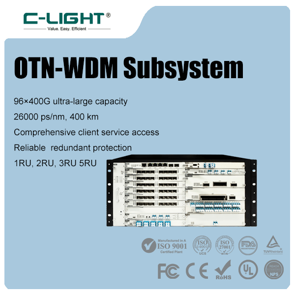
| Managed optical transport | Multi-wavelength services requiring monitoring and protection | Operational visibility, restoration, and service-level requirements |
These architectures can be combined. For example, an Ethernet interface may connect to a coherent transponder, which places the client traffic onto a DWDM wavelength for transport across a fiber line system.
4. How Optical Fiber Enables High-Capacity DCI
Optical fiber carries data as modulated light and provides high bandwidth with relatively low attenuation compared with many electrical transmission media over equivalent long distances. Single-mode fiber is widely used for data center interconnects because it supports a broad range of wavelengths and reach options.
The optical interface must match the fiber plant and intended transmission distance. Relevant factors include operating wavelength, transmitter output power, receiver sensitivity, connector loss, splice loss, dispersion, and any intermediate optical components.
Fiber type and connector condition matter just as much as nominal module speed. Contaminated connectors, excessive insertion loss, incorrect fiber polarity, or mismatched optical interfaces can cause errors or prevent a link from establishing.
Single-mode fiber: commonly used for inter-building and long-distance optical links.
Multimode fiber: generally associated with shorter-reach links inside data centers and buildings, subject to the supported optical interface.
Fiber patch cords: provide the physical connection between optical equipment, patch panels, and structured cabling.
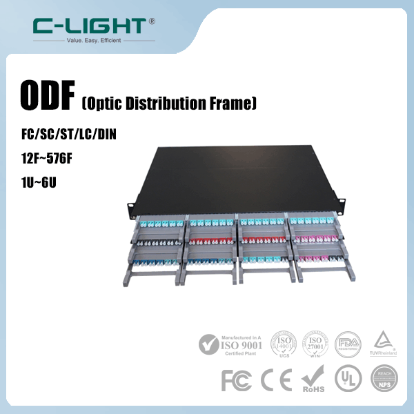
Optical distribution frames: organize fiber connections and support moves, adds, changes, and maintenance.
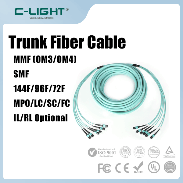
For physical connectivity planning, see C-LIGHT's indoor and outdoor fiber cable, single-mode fiber patch cord, and fiber cabling product range.
5. The Role of DWDM in Data Center Interconnectivity
Dense Wavelength Division Multiplexing (DWDM) allows multiple optical channels at different wavelengths to travel through the same fiber. Instead of requiring a separate fiber pair for every high-capacity service, a DWDM system can aggregate multiple wavelengths onto a shared fiber infrastructure.
A typical DWDM system uses transponders or transceivers, wavelength multiplexers and demultiplexers, and potentially optical amplifiers, dispersion management, and monitoring equipment. The exact components depend on the distance, optical power budget, channel plan, and line-system design.
DWDM increases the capacity that can be carried over a fiber route, but adding wavelengths is not unlimited. Channel spacing, optical signal-to-noise ratio, amplifier bandwidth, filtering, nonlinear effects, and receiver performance constrain the usable system capacity.
DWDM is especially useful where new fiber deployment is expensive or unavailable. It can also support multiple services across a common optical transport infrastructure, provided wavelength assignment and operational responsibilities are managed correctly.
Related C-LIGHT product options include DWDM optical transceivers and coherent DWDM product options. Confirm each model's data rate, wavelength tuning, reach, host interface, and line-system compatibility before deployment.
6. Coherent Optics for Regional and Long-Distance DCI
Coherent optical transmission encodes information in the amplitude and phase of an optical signal and uses coherent detection with digital signal processing to recover the transmitted data. Compared with simpler direct-detection approaches, coherent systems can support higher spectral efficiency and stronger compensation for transmission impairments in suitable designs.
Coherent optics are widely used when DCI needs high capacity over metro, regional, or longer distances. The achievable reach depends on modulation format, baud rate, forward error correction, transmitter and receiver performance, fiber characteristics, optical amplification, and the overall line system.
Coherent modules can be deployed as pluggable transceivers in compatible switches or routers, or as transponders in dedicated optical transport equipment. The choice affects integration, monitoring, power consumption, serviceability, and operational responsibilities.
7. 400G, 800G, and 1.6T in DCI Networks
Increasing traffic from cloud applications, distributed storage, and AI services is driving higher-capacity optical interfaces. However, a higher client-interface rate does not automatically mean that the same rate can be transported over every DCI line system.
| Capacity Class | Potential Role | Design Questions |
|---|---|---|
| 100G | Established inter-site links and lower-capacity services | Reach, wavelength plan, fiber availability, and upgrade path |
| 400G | High-capacity Ethernet and optical transport aggregation | Client optics versus line-side optics, host support, and optical budget |
| 800G | Higher-density cloud and data center connectivity | Port density, power, host interface, coherent options, and line-system capacity |
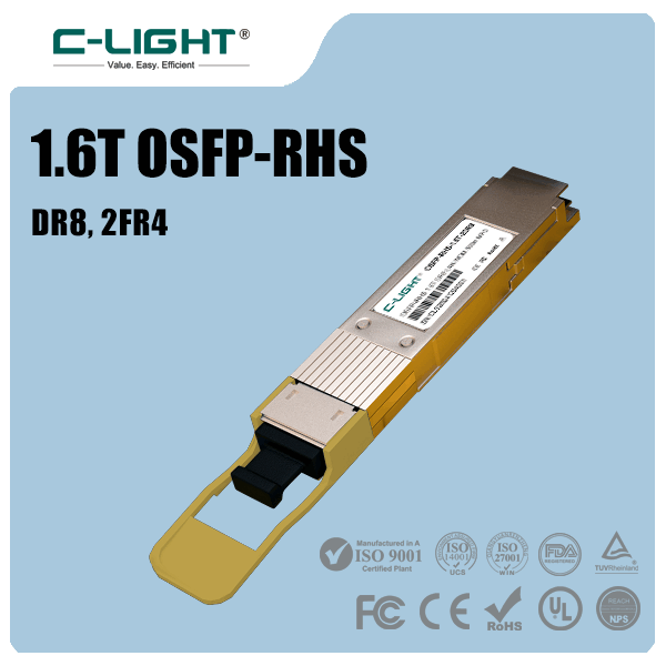
| 1.6T | Emerging high-bandwidth interfaces and next-generation interconnects | Specific implementation, electrical lanes, optical reach, interoperability, and ecosystem maturity |
Short-reach client optics and long-distance coherent line-side optics serve different roles. A data center router may use a high-speed client interface that connects to an optical transport system, while the transport system uses a different modulation format, wavelength arrangement, or line rate.
When selecting higher-speed modules, verify whether the interface is intended for direct client connectivity, a DWDM line system, or a specific optical transport platform. Do not assume that two modules with the same aggregate rate are interchangeable.
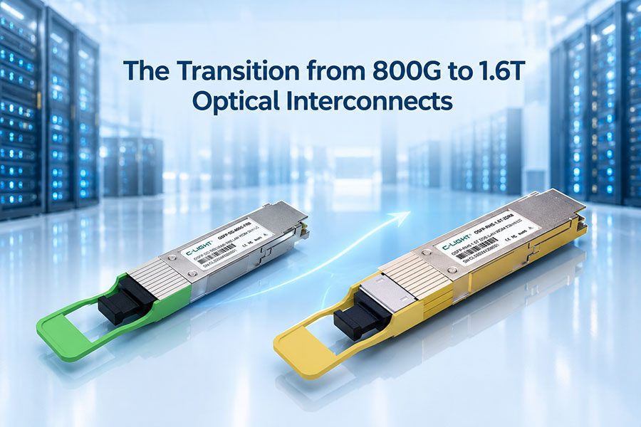
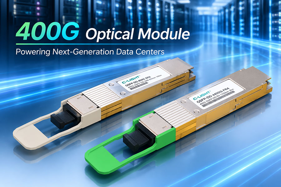
C-LIGHT's 400G QSFP-DD and 800G QSFP-DD product families provide starting points for evaluating high-speed optical connectivity. Check the individual model specifications to determine suitability for the intended DCI design.
8. Latency, Capacity, and Network Architecture
DCI performance depends on both the optical link and the network architecture above it. Optical propagation delay increases with fiber distance, while switches, routers, transponders, FEC processing, and traffic queues add further latency.
The approximate one-way propagation delay in fiber is around 5 microseconds per kilometer, although the actual end-to-end delay depends on the route, fiber path, and equipment. Geographic distance alone is therefore insufficient to predict application latency.
Capacity planning should also account for traffic patterns. Storage replication may generate sustained flows, while interactive applications may be sensitive to bursts and queueing. AI workloads can have their own traffic synchronization patterns and may require careful consideration of inter-site latency before compute resources are distributed across facilities.
Network designers should distinguish between physical optical capacity and usable application throughput. Protocol overhead, congestion, routing policies, packet loss, retransmissions, and oversubscription can reduce the throughput available to workloads.
9. Redundancy, Resilience, and Operational Monitoring
A DCI link is often a critical connection between production environments. Fiber cuts, equipment failures, power events, and configuration errors can disrupt replication or application traffic. Resilience planning should therefore include both network-level and physical-layer protection.
Route diversity: where practical, use physically diverse fiber routes to reduce the risk of a single cut affecting both primary and backup links.
Equipment redundancy: assess redundant transponders, line-system components, power supplies, and network devices according to service requirements.
Routing convergence: validate failure detection and recovery behavior so traffic can move to alternate paths when required.
Optical monitoring: track transmit and receive power, module temperature, laser bias where available, and optical signal quality metrics supported by the equipment.
Error monitoring: observe pre-FEC and post-FEC error indicators where available, as well as packet loss, latency, and throughput.
Change management: test wavelength changes, firmware upgrades, fiber moves, and maintenance procedures before applying them to critical services.
Optical power alone is not sufficient to establish link health. A link may show acceptable receive power while experiencing errors due to dispersion, reflections, interference, incorrect configuration, or other impairments. Correlating optical telemetry with FEC counters and traffic performance provides a more complete picture.
10. How to Select Optical Components for DCI
Selecting optical components begins with the service requirements and the physical route. The correct choice depends on distance, available fiber, target capacity, topology, optical budget, and the capabilities of the connected equipment.
| Selection Factor | What to Verify |
|---|---|
| Data rate and protocol | Supported Ethernet or transport interface, host lane configuration, and port compatibility |
| Transmission distance | Specified reach under the intended fiber and system conditions |
| Fiber plant | Fiber type, route loss, connectors, splices, polarity, and available fiber pairs |
| Wavelength plan | Supported wavelength or channel grid and compatibility with multiplexers and filters |
| Optical budget | Transmitter output, receiver sensitivity, total path loss, and engineering margin |
| Power and thermal limits | Module power, equipment cooling, operating temperature, and port-density constraints |
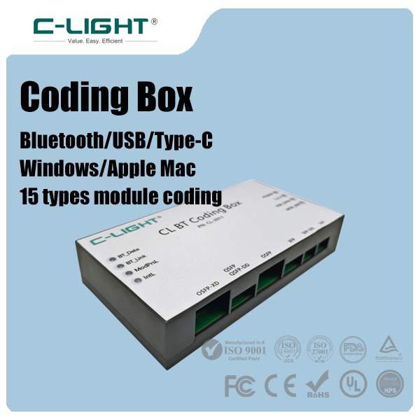
| Interoperability | Exact host model, module specification, coding requirements, and line-system compatibility |
| Future scalability | Wavelength expansion, port capacity, fiber availability, and migration options |
For optical component selection, review the C-LIGHT optical transceiver catalog alongside the relevant cabling options. Confirm the exact specifications for each module and cable before deployment.
11. Common DCI Deployment Challenges
Insufficient optical margin
A link that operates close to its optical budget may become unstable after connector changes, temperature shifts, or component aging. Design sufficient margin and verify the complete path rather than considering only the transceiver's nominal reach.
Mismatch between client and line-side interfaces
Client optics and DWDM line-side optics can use different optical specifications and transmission architectures. Validate the interface between the client equipment and the transport system before selecting components.
Limited fiber capacity
When fiber resources are constrained, DWDM can increase capacity per fiber. The available spectrum, channel plan, equipment compatibility, and line-system limitations must be evaluated before expansion.
Unexpected latency and congestion
A high-capacity optical link does not guarantee low application latency. Queueing, routing paths, traffic bursts, and oversubscription can affect performance even when the physical layer is healthy.
Incomplete monitoring
Monitoring only whether the link is up can conceal degrading optical performance. Combine transceiver telemetry, transport-system alarms, error counters, and end-to-end traffic measurements to identify issues early.
12. Conclusion
Data center interconnectivity is a critical part of distributed cloud, enterprise, storage, and AI infrastructure. High-speed optical transceivers, single-mode fiber, DWDM, and coherent transmission provide different ways to scale bandwidth across distances, from direct connections between nearby facilities to regional optical transport networks.
A successful DCI deployment requires more than choosing a higher data-rate module. Fiber-route engineering, optical budgets, wavelength planning, latency, redundancy, interoperability, and monitoring all influence the reliability and usable capacity of the connection. Selecting components against these requirements helps build a scalable interconnect that can support future bandwidth growth.
13. Frequently Asked Questions
What is the difference between DCI and DWDM?
DCI is the architecture used to connect data centers. DWDM is an optical multiplexing technology that carries multiple wavelengths over the same fiber. DWDM can be used as part of a DCI solution, but the two terms do not mean the same thing.
Does every DCI link require coherent optics?
No. Shorter links may use direct-detection Ethernet optics over dedicated fiber. Coherent optics are often selected for higher-capacity or longer-reach applications where their transmission capabilities are useful.
Can 400G or 800G optics connect two data centers directly?
Yes, if the selected optical interface supports the route's fiber type, distance, optical budget, and equipment configuration. Longer distances or wavelength-multiplexed deployments may require additional transport equipment.
Why is single-mode fiber commonly used for DCI?
Single-mode fiber supports a wide range of optical interfaces and is well suited to links extending beyond typical in-rack or short building-scale distances. The actual supported distance depends on the transceiver and link design.
How can DCI capacity be increased without installing new fiber?
Depending on the existing infrastructure, options include upgrading client interfaces, introducing DWDM, using higher-capacity coherent transmission, or improving utilization of existing wavelengths. Feasibility depends on the fiber plant, optical line system, and connected equipment.
What should be monitored on an optical DCI link?
Monitor transmit and receive optical power, temperature, supported laser diagnostics, FEC or error counters, link state, latency, packet loss, and throughput. For DWDM systems, also review wavelength-channel performance and relevant line-system alarms.
Planning a high-capacity data center interconnect?
Share your target data rate, link distance, fiber type, host equipment, and wavelength requirements to identify suitable optical connectivity options.
Contact C-LIGHT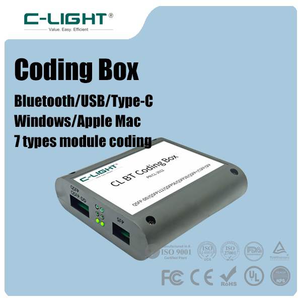 >

 >
 >
 >
 >
 >
 >
 >