TEL:+86 132 6656 7067


Data centre interconnect (DCI) provides high-capacity connections between separate data centres, campus facilities, colocation sites, cloud infrastructure, and distributed computing environments. It enables data replication, workload migration, disaster recovery, cloud connectivity, and AI data exchange across physical locations.
Modern DCI increasingly relies on single-mode fiber, 100G to 800G optical technologies, coherent transmission, and dense wavelength-division multiplexing (DWDM). The right design depends on distance, traffic demand, fiber availability, latency requirements, optical power budget, and the capabilities of the connected network equipment.
1. What Is Data Centre Interconnect?
Data centre interconnect is the network infrastructure used to transport traffic between geographically separated data centres or distinct facilities within a larger infrastructure environment. Unlike connections confined to a single rack or data hall, DCI must account for the optical path, intermediate transport equipment, route diversity, and the operational requirements of multiple sites.
DCI can be deployed over a short metropolitan fiber link or a long-haul optical network spanning hundreds of kilometres. The term describes the connectivity architecture rather than one specific transceiver, protocol, or transmission technology.
Common DCI traffic includes:
Data replication: Synchronizing databases, storage systems, and application data between sites.
Disaster recovery: Maintaining a remote copy of critical data and supporting service recovery.
Cloud connectivity: Connecting enterprise infrastructure with cloud platforms and colocation environments.
Workload migration: Moving virtual machines, containers, and application services between facilities.
AI and distributed computing: Transporting datasets, checkpoints, model artifacts, and other traffic between computing locations.
Network expansion: Extending capacity when an existing data centre reaches its space, power, or infrastructure limits.
2. How a DCI Architecture Works
A DCI system connects optical interfaces at two or more sites through a fiber path. Depending on the design, the optical signals may pass through amplification, wavelength multiplexing, optical switching, dispersion-related impairment management, or other transport functions before reaching the destination.
| Architecture Layer | Primary Function | Typical Considerations |
|---|---|---|
| Client network | Generates and receives Ethernet, storage, or other client traffic | Port speed, interface type, routing, switching, and traffic patterns |
| Optical interface | Converts electrical client signals into optical signals and back | Form factor, wavelength, modulation, reach, and interoperability |
| Optical transport | Carries signals over the fiber infrastructure | Fiber attenuation, connector loss, OSNR, dispersion, and optical power |
| Wavelength management | Combines or separates multiple optical channels when required | Channel spacing, wavelength plan, mux/demux loss, and filtering |
| Resilience and operations | Maintains service availability and supports fault isolation | Route diversity, protection, monitoring, and restoration procedures |
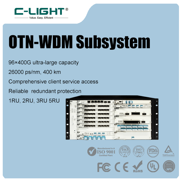
Some short-reach DCI connections use optical transceivers directly between network devices. Longer or higher-capacity links may use a dedicated optical transport system, including DWDM equipment and line amplifiers. In other deployments, coherent optics connect directly to routers or switches, reducing the need for separate transponder equipment when the interface and optical line system support that configuration.
3. DCI Distance Categories and Deployment Scenarios
DCI distances are often grouped into campus, metropolitan, regional, and long-haul deployments. These categories are useful for initial planning, but there is no universal distance boundary for every design. Actual reach depends on the selected optical interface, fiber route, line system, and engineering margin.
| Deployment Scenario | Approximate Distance | Common Technology Choices | Key Design Priority |
|---|---|---|---|
| Campus DCI | Hundreds of metres to a few kilometres | Client-side Ethernet optics over single-mode fiber; multimode fiber for suitable short links | Cost, simplicity, and physical routing |
| Metropolitan DCI | Several to tens of kilometres | 100G, 400G, or higher-speed single-mode optics; coherent interfaces where appropriate | Fiber availability, capacity, and optical budget |
| Regional DCI | Tens to a few hundred kilometres | Coherent optics, DWDM, and transport equipment as required | OSNR, optical amplification, and route engineering |
| Long-haul DCI | Several hundred kilometres or more | Coherent DWDM systems with engineered optical line infrastructure | End-to-end optical performance, protection, and operational cost |
These ranges are indicative rather than guaranteed reach specifications. A module rated for a particular distance does not automatically support that distance through every installed fiber route. Connector loss, splices, intermediate optical components, fiber quality, and the receiving system all affect the achievable link performance.
4. Optical Transceivers for 100G, 400G and 800G DCI
Optical transceivers determine how network equipment transmits and receives data over fiber. DCI deployments may use 100G, 400G, or 800G interfaces depending on port availability, aggregate traffic, fiber capacity, and the distance between sites.
100G optical connectivity
100G interfaces remain relevant for existing metropolitan networks, enterprise interconnection, cloud access, and incremental capacity expansion. Depending on the application, designs may use parallel-fiber optics, multiple wavelengths, or coherent transmission. The choice should be based on the actual interface specification and optical path rather than the data rate alone.
400G optical connectivity
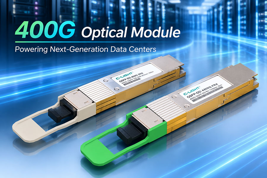
400G supports higher aggregate bandwidth per port and can reduce the number of interfaces required for a given traffic volume. Shorter links may use client-side Ethernet optics, while longer metropolitan and regional connections may use suitable coherent interfaces or a dedicated DWDM transport system.
800G optical connectivity
800G provides additional capacity for large-scale cloud infrastructure, AI-related traffic exchange, and data centre expansion. Its practical deployment depends on compatible host ports, supported optical interfaces, thermal limits, fiber infrastructure, and the available transmission budget. An 800G client optic should not be assumed to provide long-haul coherent transmission simply because its aggregate rate is high.
5. Why DWDM Is Important for DCI
Dense wavelength-division multiplexing (DWDM) carries multiple optical channels at different wavelengths through the same fiber pair. Instead of deploying a separate fiber pair for every traffic channel, a DWDM system combines multiple wavelengths onto a shared fiber path and separates them at the receiving end.
This approach is valuable where fiber resources are limited, leasing additional fiber is expensive, or traffic demand is growing faster than physical infrastructure can be expanded.
Key DWDM functions include:
Wavelength multiplexing: Combines multiple optical channels onto a common fiber path.
Wavelength demultiplexing: Separates the channels at the destination.
Optical amplification: Compensates for transmission loss where the optical design requires it.
Channel planning: Coordinates wavelength allocation, spacing, filtering, and supported optical power levels.
Capacity scaling: Adds supported wavelengths or upgrades channel rates when the system has sufficient capacity.
DWDM is not the same as DCI itself. DCI describes the interconnection architecture, while DWDM is one technology that can increase the capacity of the optical transport layer. Some DCI links operate without DWDM, and a DWDM system can also support applications beyond data centre interconnection.
6. Coherent Optics for Metropolitan and Long-Haul DCI
Coherent optical transmission uses information encoded in optical signal properties, together with coherent detection and digital signal processing, to recover high-capacity data streams. It is widely used when the optical path requires greater reach or spectral efficiency than conventional short-reach direct-detection interfaces can provide.
Coherent DCI solutions may use dedicated transponders or coherent pluggable transceivers connected directly to supported routers and switches. The latter approach can simplify network architecture when the host interface, software, optical power, and line-system requirements are aligned.
Important design variables include:
Modulation format: Influences spectral efficiency and tolerance to transmission impairments.
Optical signal-to-noise ratio (OSNR): A key factor in determining whether the receiver can recover the transmitted data.
Forward error correction (FEC): Provides error-correction capability within the supported system design.
Fiber attenuation and dispersion: Affect the optical signal as it travels through the link.
Amplifier configuration: Influences noise accumulation and the overall optical power profile.
Line-system compatibility: Determines whether a coherent interface can operate within the intended wavelength plan and optical operating range.
Coherent transmission does not guarantee a specific reach in isolation. The achievable distance depends on the transceiver and its operating mode, the fiber route, optical amplifiers, intermediate components, and the engineering limits of the complete link.
7. Fiber Infrastructure and Optical Link Budget
Single-mode fiber is commonly used for metropolitan, regional, and long-haul DCI because it supports long-distance transmission and a broad range of optical interfaces. Multimode fiber can remain suitable for certain short campus connections, but its use depends on the interface specification and installed cabling.
Before selecting an optical transceiver, engineers should calculate the loss of the complete optical path and verify that it falls within the transmitter and receiver specifications.
Basic optical loss calculation:
Total link loss = Fiber attenuation + Connector loss + Splice loss + Passive component loss
Available power margin = Transmitter output power − Total link loss − Receiver sensitivity
This simplified calculation is useful for an initial power-budget check. The final design must also account for the transceiver's specified operating conditions, engineering margin, connector cleanliness, aging considerations, and any additional optical-system constraints.
A link with excessive loss may experience low received optical power or fail to meet the required error performance. Conversely, excessive received power can overload a receiver if it exceeds the specified input range. Optical power should therefore be checked against both minimum and maximum receiver limits.
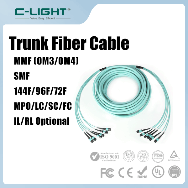
Related fiber infrastructure includes fiber optic cables and connectivity products for building, campus, and inter-facility deployments. Cable selection should consider fiber type, installation environment, connector interface, route protection, and applicable local requirements.
8. Latency, Availability and Network Resilience
DCI performance is determined by more than optical line rate. Propagation delay, switching and routing behavior, congestion, buffering, retransmissions, and the application traffic pattern can all influence end-to-end performance.
Fiber propagation delay is an important consideration for geographically distributed applications. Increasing bandwidth does not eliminate the physical delay associated with a longer route. Storage replication, synchronous transactions, and distributed applications may have strict latency requirements that limit the practical distance between facilities.
High-availability DCI designs may incorporate:
Physically diverse routes: Separate fiber paths to reduce exposure to a common cable cut or shared infrastructure failure.
Redundant optical equipment: Backup interfaces, transponders, line cards, or transport devices where required.
Network-level redundancy: Alternative paths and routing policies that support recovery from link or device failures.
Optical monitoring: Tracking received power, error counters, FEC statistics, and other available diagnostics.
Operational testing: Validating failover behavior, restoration time, and application recovery procedures.
Two circuits should not be treated as fully diverse merely because they use different ports or wavelengths. If they share the same conduit, building entrance, amplifier site, or other critical infrastructure, a single physical incident may affect both.
9. DCI for AI Data Centres and Distributed Computing
AI infrastructure increases demand for high-capacity networking as organizations distribute storage, compute resources, data preparation, model serving, and other workloads across multiple facilities. DCI can connect separate AI data centres, provide access to remote datasets, and support replication of model checkpoints and training artifacts.
However, interconnecting facilities is not equivalent to creating one low-latency scale-up fabric. The network architecture must match the application's communication pattern, transport requirements, and tolerance for delay.
| AI Workload | DCI Requirement | Primary Engineering Consideration |
|---|---|---|
| Dataset transfer | High sustained throughput | Aggregate bandwidth, transfer scheduling, and storage performance |
| Checkpoint replication | Reliable transfer of large data volumes | Recovery objectives, write consistency, and available capacity |
| Distributed inference | Predictable service connectivity | Latency, routing, traffic isolation, and service availability |
| Multi-site resource coordination | Inter-site network and control-plane connectivity | Failure handling, application placement, and operational complexity |
For tightly coupled distributed training, communication latency and synchronization behavior can be as important as raw bandwidth. Many latency-sensitive collective communication patterns are best kept within a purpose-built cluster fabric. DCI is more commonly used to connect separate facilities and support workloads whose requirements fit the inter-site network.
10. Power, Thermal Management and Rack Density
Higher-speed DCI interfaces can increase port density, but system power and cooling must be evaluated across the complete deployment. Relevant factors include transceiver power, host port consumption, optical transport equipment, amplification, chassis capacity, and the thermal conditions around installed modules.
Higher data rates do not automatically produce lower energy consumption per bit. Efficiency depends on the optical technology, the number of components required, link distance, system utilization, and the power consumed by both client and line-side equipment.
For high-density deployments, engineering teams should verify:
Supported transceiver power and host thermal limits.
Airflow direction, heatsink clearance, and chassis cooling capacity.
Optical module compatibility with the intended switch, router, or transport platform.
Power requirements for amplifiers, mux/demux systems, and other line-side equipment.
Monitoring thresholds and operating margins under expected environmental conditions.
11. How to Select DCI Optical Components
Choosing a DCI transceiver requires a complete view of the interface, distance, fiber path, optical architecture, and host equipment. Matching only the nominal data rate can lead to incompatibility or a link that does not meet the required performance.
| Selection Factor | What to Verify |
|---|---|
| Data rate | Required port speed and whether it is supported by the host and remote interface |
| Form factor | Physical slot, module type, port configuration, and host platform support |
| Transmission distance | Specified reach under the actual fiber and optical-system conditions |
| Fiber type | Single-mode or multimode fiber, installed cable characteristics, and connector type |
| Wavelength plan | Required operating wavelength, channel spacing, and compatibility with multiplexers or line systems |
| Optical budget | Transmitter power, receiver sensitivity, maximum input power, and total path loss |
| Host compatibility | Supported module specifications, software requirements, and platform restrictions |
| Environmental conditions | Power consumption, operating temperature, airflow, and installation requirements |
| Resilience | Route diversity, backup interfaces, monitoring, and recovery requirements |
For platform-specific deployments, confirm the exact switch or router model, software version, required interface type, and the optical system at both ends. A transceiver that uses the same form factor as another module is not necessarily interchangeable in every platform or application.
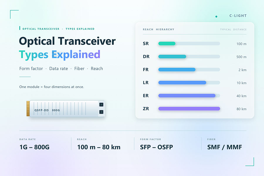
Browse the optical transceiver product range for interface options across different network applications. Final selection should be based on the specific product datasheet and the requirements of the complete DCI link.
12. Common DCI Deployment Problems
DCI faults can originate in the optical path, transceiver, host configuration, or network layer. A structured troubleshooting process helps distinguish physical-layer issues from routing, congestion, and application problems.
Low received optical power
Possible causes include excessive fiber attenuation, dirty connectors, damaged patch cords, unexpected splice loss, or passive components with higher-than-expected insertion loss. Inspect and clean connectors using approved procedures, verify the optical path, and compare measured power against the transceiver specifications.
High error rates or unstable links
Check module diagnostics, FEC counters, interface error statistics, optical power, and the relevant host logs. Depending on the technology, the cause may involve marginal optical performance, a compatibility issue, an unsuitable fiber path, or a configuration mismatch.
DWDM channel issues
Verify wavelength assignments, mux/demux connections, channel spacing, optical power levels, and compatibility with the line system. For coherent interfaces, also examine OSNR and the supported operating parameters.
Insufficient throughput
A link that reports an operational status may still fail to deliver expected application throughput. Investigate congestion, interface errors, MTU consistency, routing paths, packet loss, traffic shaping, and endpoint performance before attributing the problem to the optical module alone.
Unexpected service interruption
Review physical alarms, interface state changes, route events, equipment logs, and redundancy behavior. Confirm that protection paths are genuinely independent and that failover procedures have been tested under realistic operating conditions.
13. Future Development of Data Centre Interconnect
DCI continues to evolve as data centre traffic grows and operators seek greater capacity from existing fiber infrastructure. Higher-speed client interfaces, coherent pluggables, DWDM channel upgrades, and more integrated optical solutions are expanding the available design choices.
Key development directions include:
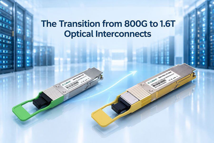
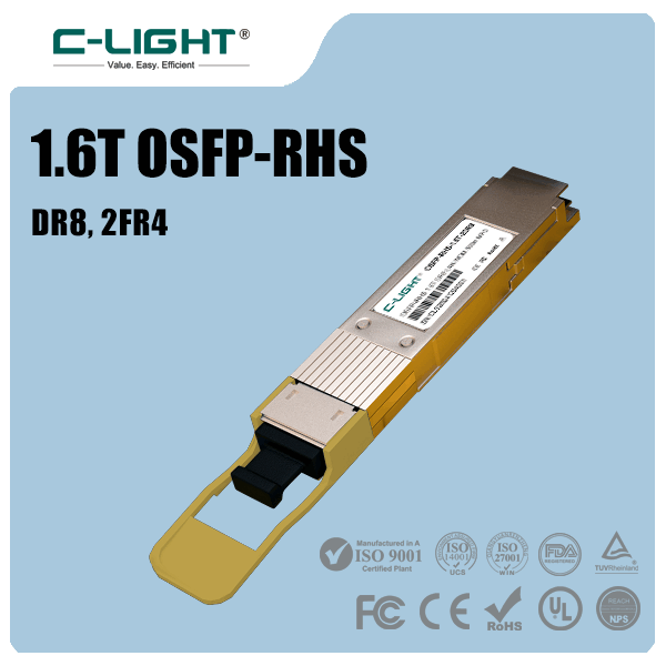
Higher-capacity interfaces: Progression from established 100G and 400G deployments toward 800G and emerging 1.6T connectivity where supported by the ecosystem.
Coherent pluggables: Integration of coherent transmission into supported networking platforms to simplify selected transport architectures.
Improved fiber utilization: More efficient use of available spectrum and existing fiber routes through suitable DWDM systems.
Greater operational visibility: Expanded use of telemetry, optical diagnostics, and automated fault analysis.
AI-driven capacity planning: Traffic forecasting and workload-aware network design for distributed computing environments.
Energy-aware network engineering: Evaluating power consumption across client optics, line systems, and the complete network rather than considering transceiver power in isolation.
Future capacity upgrades will still depend on more than the optical module itself. Host interfaces, fiber infrastructure, line-system limits, cooling, operational requirements, and interoperability must be evaluated together to determine whether an upgrade is practical.
14. Frequently Asked Questions
DCI is the architecture that connects data centres. DWDM is an optical multiplexing technology that carries multiple wavelength channels over shared fiber infrastructure and can be used to implement high-capacity DCI links.
No. Shorter links may use suitable direct-detection Ethernet optics. Coherent optics are particularly useful for many metropolitan, regional, and long-haul applications where their reach and spectral-efficiency characteristics are beneficial.
Yes, when the specific optical interface supports the intended distance and fiber conditions and is compatible with the connected equipment. The data rate alone does not determine transmission reach.
Single-mode fiber is widely used for metropolitan and longer-distance interconnection. Multimode fiber may be suitable for selected short campus links when supported by the chosen optical interface.
Use appropriately engineered optical budgets, qualified equipment, clean connectors, continuous monitoring, diverse physical routes where required, and tested network recovery procedures.
No. Performance also depends on latency, congestion, error rates, routing, optical signal quality, endpoint capability, and application traffic patterns.
15. Conclusion
Data centre interconnect is a fundamental part of distributed cloud, enterprise, storage, and AI infrastructure. A successful DCI deployment combines the right optical interfaces with appropriate fiber engineering, wavelength management, transport technology, network resilience, and operational monitoring.
For short connections, direct optical links may provide a straightforward solution. As distance and capacity requirements increase, DWDM and coherent transmission can help operators scale network capacity while making efficient use of existing fiber infrastructure. The most suitable design is the one that meets the required bandwidth, reach, reliability, and power targets under real operating conditions.
Planning a high-speed optical interconnect deployment?
Review the optical interface, reach, fiber type, and host compatibility requirements before selecting components for your network.
Contact C-LIGHT >

 >
 >
 >
 >
 >
 >
 >