TEL:+86 132 6656 7067


AI data centers are increasing both compute density and network bandwidth. GPU clusters, high-radix switches and high-speed optical interconnects generate substantial heat within increasingly compact equipment layouts. As a result, liquid cooling is becoming an important part of infrastructure design, while optical transceivers must operate reliably within the thermal and mechanical conditions of these systems.
Optical connectivity in liquid-cooled environments requires more than a high data rate. Module materials, enclosure design, connector interfaces, cable routing, thermal transfer and coolant compatibility all influence deployment suitability. For 400G, 800G and 1.6T AI networks, optical module selection must be coordinated with the server, switch and cooling architecture.
1. Optical Connectivity in Liquid-Cooled AI Infrastructure
AI training and inference clusters rely on high-bandwidth connections between GPUs, network switches, storage systems and compute nodes. Ethernet and InfiniBand fabrics provide the communication paths required for distributed workloads, while optical transceivers convert high-speed electrical signals into optical signals for transmission across fiber.
In traditional air-cooled systems, transceivers are generally designed to operate within an airflow environment around the switch or server faceplate. Liquid-cooled systems introduce different thermal and mechanical conditions. Depending on the architecture, a module may be installed in an air-cooled section, coupled to a cold plate, or exposed directly to an immersion cooling fluid.
These configurations require different engineering approaches. A module suitable for a cold-plate environment is not automatically suitable for direct immersion, and a conventional air-cooled transceiver should not be assumed to tolerate continuous exposure to cooling liquid.
2. Liquid Cooling Architectures for AI Data Centers
Liquid cooling includes several system architectures. The location of the cooling interface and the components exposed to liquid determine the requirements for optical transceivers, cages, connectors and fiber assemblies.
| Cooling Architecture | Cooling Method | Optical Module Environment | Primary Design Requirement |
|---|---|---|---|
| Direct-to-chip liquid cooling | Coolant circulates through cold plates attached to processors and selected heat-generating components. | Optical modules may remain in an air-cooled or separately managed switch environment. | Coordinate module thermal limits with rack airflow and cold-plate layout. |
| Liquid-cooled switch or module assembly | A liquid cooling structure removes heat from selected switch or optical components. | Modules may use a dedicated thermal interface or engineered cooling structure. | Verify mechanical contact, thermal resistance and service access. |
| Single-phase immersion cooling | Electronic equipment is immersed in a dielectric liquid that remains in liquid form during operation. | Exposed module surfaces and optical assemblies contact the cooling fluid. | Validate material compatibility, sealing and long-term fluid exposure. |
| Two-phase immersion cooling | A dielectric fluid changes phase as it absorbs heat and condenses within the cooling system. | Components operate in a fluid environment with additional phase-change conditions. | Evaluate fluid compatibility, pressure conditions and thermal cycling. |
Direct-to-chip cooling and immersion cooling should not be treated as equivalent. In direct-to-chip systems, the cooling liquid is normally contained within a dedicated circuit and does not directly contact the optical transceiver. In immersion systems, exposed module surfaces and cable assemblies may be continuously surrounded by dielectric fluid.
3. Why High-Speed Optical Modules Require Advanced Thermal Design
Higher optical data rates increase the complexity of signal processing and optical integration. Transmitters, receivers, DSPs, laser drivers and power-management circuits all contribute to module power consumption. As port density increases, the combined thermal load around switch faceplates can become a significant design constraint.
800G and 1.6T optical modules are particularly relevant to AI infrastructure because they support high-capacity switch-to-switch and accelerator-network connections. Their thermal requirements depend on the optical architecture, lane rate, DSP implementation, laser technology, form factor and operating conditions.
DSP and signal processing: High-speed electrical and optical signal processing contributes to module power consumption.
Laser and receiver circuits: Optical transmit and receive components generate heat during continuous operation.
High port density: Multiple modules installed in one switch create concentrated heat around the front panel.
Host interface: Electrical interface losses and surrounding switch components add to the overall thermal environment.
Cooling contact: Thermal performance depends on the contact area, material properties and cooling-system design.
Liquid cooling can improve heat removal at the system level, but it does not automatically eliminate the thermal limitations of an optical transceiver. Module case temperature, internal component temperature, power consumption and thermal resistance still need to be evaluated against the product specification.
4. 400G, 800G and 1.6T Optical Modules for AI Networks
AI data center networks are moving toward higher-speed optical interfaces to support greater east-west traffic between accelerators and switches. Different module generations provide different lane configurations, modulation formats and optical reaches.
| Data Rate | Common Form Factors | Representative Lane Architecture | AI Network Application |
|---|---|---|---|
| 400G | QSFP-DD, OSFP, QSFP112 | 4 × 100G or 8 × 50G electrical/optical lane architectures, depending on implementation | Switch uplinks, GPU cluster interconnects and leaf-spine connections |
| 800G | OSFP, QSFP-DD | 8 × 100G or 4 × 200G PAM4, depending on module design | High-density AI fabrics and high-capacity switch connections |
| 1.6T | OSFP and next-generation high-speed interfaces | 8 × 200G PAM4 | Next-generation AI switches and higher-capacity cluster networks |
The lane architectures shown are representative rather than universal. Actual electrical and optical lane arrangements depend on the module standard and product implementation. Connector type, reach and fiber architecture must also be selected according to the intended link.
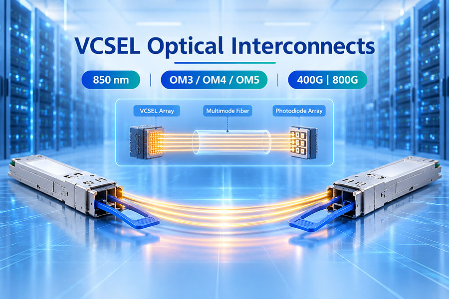
For example, 800G SR8 and DR8 modules serve different fiber environments, while 2×FR4 configurations use wavelength multiplexing over duplex single-mode fiber. At 1.6T, 8 × 200G PAM4 designs increase the importance of signal integrity, DSP performance and thermal engineering.
5. Form Factor Selection: QSFP-DD, OSFP and OSFP-RHS
Optical module form factors define mechanical dimensions, electrical interfaces, thermal interfaces and host compatibility. Liquid-cooled AI systems must consider these characteristics alongside optical performance.
| Form Factor | Typical Application | Thermal Considerations | Integration Requirements |
|---|---|---|---|
| QSFP-DD | 400G and selected 800G optical interfaces | Depends on module power and host cooling design. | Verify cage, connector, module power and management compatibility. |
| OSFP | 800G and next-generation high-speed optical interfaces | Designed for higher-power applications with form-factor-specific thermal provisions. | Confirm host cage, heat sink, airflow or liquid-cooling integration. |
| OSFP-RHS | High-density applications using reduced-height heat sink designs | Mechanical and thermal design must match the host cooling architecture. | Check reduced-height clearance and host-specific cooling arrangements. |
| QSFP112 | High-speed 400G-class optical and electrical interfaces | Thermal limits depend on the module and host implementation. | Verify the exact interface generation and equipment support. |
OSFP-RHS designs use a reduced-height heat sink structure intended for specific high-density equipment configurations. This mechanical feature should not be interpreted as proof of direct immersion compatibility. The complete module construction and cooling environment must still be qualified.
6. Immersion-Compatible Optical Transceiver Design
An optical transceiver intended for direct immersion must be evaluated as a complete assembly rather than only as an optical engine inside a standard housing. Materials that perform normally in air may behave differently after prolonged exposure to dielectric fluids.
Important design areas include:
Housing materials: The enclosure must retain its mechanical and chemical properties in the specified cooling fluid.
Sealing structure: Seals and interfaces must prevent unwanted fluid ingress into protected areas.
PCB and component materials: Coatings, solder materials, adhesives and other exposed materials require compatibility evaluation.
Optical connector interface: Connector materials and optical alignment must remain suitable under the intended operating conditions.
Labeling and identification: Markings and labels must remain legible and securely attached after fluid exposure.
Mechanical retention: Latches, pull tabs and cage interfaces must remain functional during installation and removal.
Thermal transfer: The module must maintain acceptable internal operating temperatures in the target cooling environment.
Immersion compatibility is specific to the cooling fluid and operating conditions. A module validated with one dielectric liquid should not automatically be assumed compatible with another formulation. Material screening and system-level qualification are necessary before deployment.
7. Cold-Plate Cooling and Optical Module Thermal Interfaces
Cold-plate cooling removes heat through a liquid-cooled metal plate connected to selected components. In optical systems, thermal interfaces may be designed to transfer heat from the module or host assembly toward a cold plate without exposing the optical transceiver to the circulating coolant.
The mechanical relationship between the module, cage, heat sink and cold plate is important. Incorrect contact pressure, surface flatness or thermal interface material selection can reduce heat transfer and create uneven temperature distribution.
Engineering considerations include:
Thermal contact area and interface resistance.
Cold-plate geometry and mounting position.
Mechanical tolerance between the module and cooling structure.
Thermal interface material durability and compatibility.
Host airflow requirements for components outside the liquid-cooled area.
Service access for module replacement and cold-plate maintenance.
Cold-plate cooling is a system-level thermal solution. The transceiver's operating limits must still be checked under the actual host configuration, including the worst-case module power and expected coolant temperature.
8. Optical Fiber and Connector Design in Immersion Environments
Optical connectivity in liquid-cooled systems extends beyond the transceiver itself. Fiber cables, connectors, adapters, strain relief components and cable routing structures may also be exposed to cooling fluid or pass through boundaries between immersed and non-immersed areas.
Multimode fiber is commonly used for short-reach optical connections within equipment environments. Single-mode fiber supports longer links and a wider range of optical transport architectures. The selected fiber type depends on the module interface, required reach and network topology.
| Optical Interface | Typical Fiber Type | Application | Design Consideration |
|---|---|---|---|
| LC duplex | Single-mode or multimode | Duplex optical links and short equipment connections | Connector material, fluid exposure and cable routing. |
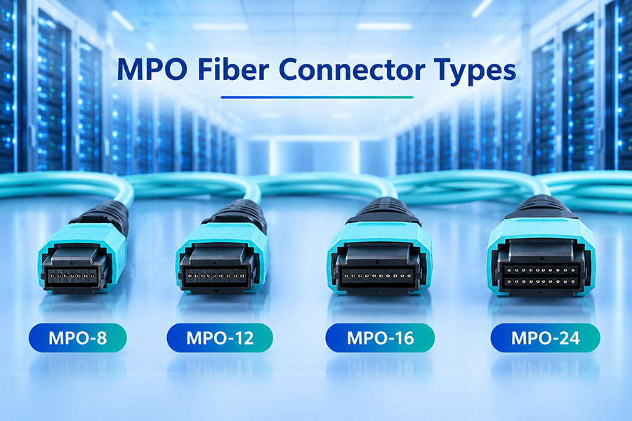
| MPO/MTP | Multimode or single-mode parallel fiber | 400G, 800G and multi-lane optical connections | Polarity, alignment, cleaning and connector protection. |
| UniBoot LC | Multimode or single-mode, according to the assembly | Compact duplex cable routing | Boot material, bend radius and mechanical retention. |
| Custom optical pigtail | Application-dependent | Immersion-compatible or specialized equipment interconnects | Material compatibility, length and installation path. |
Cable routing must account for the complete path from the transceiver to the next optical connection point. Tank penetrations, cable slack, bend radius, strain relief and service access should be included in the mechanical layout.
9. Power Consumption and System-Level Thermal Efficiency
Optical transceiver power consumption contributes to the total thermal load of AI switches and network systems. As the number of high-speed ports increases, even small differences in module power can affect the aggregate heat generated around a switch.
The relationship between module power and cooling efficiency should be evaluated at the system level. A lower-power transceiver reduces electrical consumption and heat generation, while an effective cooling architecture improves heat removal from the equipment. These are related but separate engineering factors.
| Parameter | Effect on the System | Evaluation Method |
|---|---|---|
| Module power consumption | Contributes to electrical demand and local heat generation. | Measure or verify power at the intended operating condition. |
| Module temperature | Influences component operating margins and reliability. | Monitor case temperature and relevant internal diagnostics. |
| Thermal resistance | Determines how effectively heat moves from the module to the cooling medium. | Evaluate the complete thermal path and interface materials. |
| Cooling capacity | Determines the system's ability to remove generated heat. | Review coolant flow, inlet temperature and heat-exchanger capacity. |
| Port density | Influences the concentration of heat around the switch faceplate. | Evaluate aggregate module power across populated ports. |
Cooling efficiency should not be measured only by the temperature of the optical module. Electrical power, coolant pumping requirements, heat-exchanger efficiency and facility-level cooling overhead all contribute to the overall energy profile of the data center.
10. Optical Link Budget and Signal Integrity
Liquid cooling changes the thermal environment, but it does not remove the optical requirements of the communication link. Transmitter power, receiver sensitivity, fiber attenuation, connector loss and optical reflections remain important factors in maintaining reliable high-speed transmission.
A simplified optical power budget is calculated as follows:
Available Optical Power Budget (dB) = Minimum Tx Output Power (dBm) − Receiver Sensitivity (dBm)
The total link loss must remain within the available budget, with an engineering margin for installation variation and future degradation. For parallel-fiber modules, each optical lane must meet the relevant optical requirements. For WDM configurations, wavelength-specific loss and channel performance must also be considered.
Verify transmitter output power and receiver sensitivity at the specified operating rate.
Confirm the optical lane mapping and connector polarity.
Inspect fiber connectors for contamination before installation.
Measure insertion loss across the complete optical path.
Check receiver overload limits where short links or high optical power are involved.
Evaluate BER and interface error counters under the intended operating conditions.
Optical performance testing should be conducted after the final module, cable and host configuration has been assembled. A module that passes standalone testing may still encounter system-level issues caused by connector routing, mechanical constraints or host compatibility.
11. Material Compatibility and Reliability Qualification
Material compatibility is one of the most important qualification requirements for direct immersion applications. Dielectric fluids differ in chemical composition and may interact differently with plastics, elastomers, coatings, adhesives, cable jackets and metal finishes.
A qualification program should identify every material exposed to the cooling fluid and evaluate its behavior under the intended temperature, exposure duration and operating conditions.
| Qualification Area | Test Objective | Potential Failure Concern |
|---|---|---|
| Fluid compatibility | Evaluate exposed materials in the specified coolant. | Swelling, discoloration, degradation or material changes. |
| Sealing performance | Verify protection of designated internal areas. | Fluid ingress or seal deterioration. |
| Optical performance | Check transmission and reception before and after exposure. | Optical loss variation or connector degradation. |
| Thermal cycling | Evaluate operation across the specified temperature range. | Mechanical stress or changes in optical alignment. |
| Mechanical durability | Verify retention, insertion and removal functions. | Latch damage, housing deformation or connector movement. |
| Electrical reliability | Confirm stable electrical operation after environmental testing. | Intermittent contacts or electrical performance degradation. |
Qualification results should be documented for the exact module configuration and coolant. Changes to the fluid formulation, cable assembly, enclosure materials or operating temperature may require additional validation.
12. DDM Monitoring and Maintenance in Liquid-Cooled Systems
Digital Diagnostic Monitoring provides information about the operating conditions of supported optical modules. Temperature, voltage, laser bias current, Tx optical power and Rx optical power can help identify abnormal conditions during system operation.
Temperature: Tracks module operating temperature and helps identify thermal conditions outside the expected range.
Supply voltage: Provides information about electrical power conditions.
Laser bias current: Helps monitor transmitter operating behavior.
Tx optical power: Indicates the measured transmit signal level.
Rx optical power: Helps identify changes in received optical signal strength.
In liquid-cooled systems, DDM should be combined with cooling-system monitoring. Coolant inlet temperature, flow rate, pressure and leak-detection information provide additional system context that an optical module cannot measure independently.
Maintenance procedures should also account for the cooling architecture. In an immersion tank, module replacement may require a defined removal process, fluid handling procedures and post-service inspection. Optical connector cleaning and cable routing should follow the equipment manufacturer's instructions.
13. C-LIGHT Liquid Immersion Optical Transceiver Solutions
C-LIGHT provides optical connectivity solutions for AI data centers, high-performance computing and high-density computing environments. Its liquid immersion optical transceiver product range is designed for short-reach multimode connections in immersion cooling applications.
Liquid Immersion 100G QSFP28 to MPO
Product code: CL100GS4MUIM0.8M. This configuration uses 850nm multimode optics, OM3 fiber and an MPO interface, with a specified 0.8m connection length and industrial-temperature designation.
Liquid Immersion 25G/10G SFP28 to UniBoot LC
Product code: CL25GSLUB-IM0.8M. This configuration supports 25G/10G optical connectivity using 850nm multimode transmission, OM3 fiber and a UniBoot LC connection, with a specified 0.8m connection length and industrial-temperature designation.
These short-reach configurations address optical connections within liquid-cooled computing environments. For other data rates, form factors, cable lengths or cooling-fluid requirements, the exact configuration and compatibility should be confirmed before deployment.
View the C-LIGHT Liquid Immersion Optical Transceiver product page for available configurations.
14. Engineering Considerations for 800G and 1.6T Liquid-Cooled Networks
The transition to 800G and 1.6T increases the importance of optical module power, signal integrity and thermal integration. AI switches with high port counts can concentrate substantial optical power consumption around a limited physical area. Liquid cooling may become part of the thermal strategy, but high-speed optical modules still require product-specific qualification.
At 800G, common optical architectures include SR8, DR8 and 2×FR4. At 1.6T, 8 × 200G PAM4 lane architectures provide a path toward higher aggregate bandwidth. These configurations differ in optical lane count, fiber arrangement, connector requirements and signal-processing implementation.
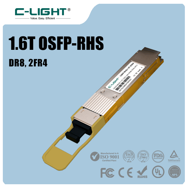
C-LIGHT's 800G OSFP, 800G QSFP-DD and 1.6T OSFP-RHS product categories address high-speed AI and data center interconnect requirements. Their suitability for a particular liquid-cooling architecture must be verified against the exact module configuration and cooling environment.
For immersion deployments, confirmation should cover the coolant type, exposed materials, sealing structure, operating temperature, optical cable assembly and service procedure. A high-speed data rate or a reduced-height heat sink design alone does not establish immersion compatibility.
15. Integration Checklist for Liquid-Cooled AI Data Centers
Optical module selection should be coordinated with the data center's mechanical, electrical, thermal and network design teams. The following items provide a practical engineering checklist for qualification and deployment.
Identify whether the system uses direct-to-chip cooling, cold-plate cooling or immersion cooling.
Confirm the exact optical module form factor and host interface.
Specify the required data rate, optical reach and protocol.
Confirm single-mode or multimode fiber and the required connector type.
Identify the exact cooling fluid for direct immersion applications.
Review all materials exposed to the coolant, including cables and connectors.
Validate thermal performance under the intended module power and cooling conditions.
Check optical budget, connector loss, polarity and cable routing.
Confirm DDM support and system-level monitoring requirements.
Define installation, removal, cleaning and maintenance procedures.
Complete sample qualification before volume deployment.
16. Conclusion
Optical transceivers are essential to the high-bandwidth networks used in liquid-cooled AI data centers. As AI clusters move toward 400G, 800G and 1.6T connectivity, optical module design must account for both transmission performance and the thermal environment in which the equipment operates.
Direct-to-chip cooling, cold-plate cooling and immersion cooling introduce different requirements for optical module installation and qualification. In particular, immersion-ready transceivers require evaluation of exposed materials, sealing, coolant compatibility, optical interfaces and long-term operating behavior.
Reliable deployment depends on coordinated engineering across optical performance, mechanical design, thermal management, fiber integration and maintenance. Selecting modules according to the exact cooling architecture helps AI data centers build higher-density interconnects while maintaining stable network operation.
Looking for optical transceivers for liquid-cooled AI data centers?
Contact C-LIGHT for liquid immersion optical connectivity, product specifications and customized optical solutions.
Contact C-LIGHT >

 >
 >
 >
 >
 >
 >
 >