TEL:+86 132 6656 7067


Mobile transport networks require optical connectivity that can accommodate increasing radio capacity, distributed baseband processing and growing traffic between access sites and the mobile core. High-speed optical modules provide the physical interfaces for these connections, supporting different data rates, transmission distances and fiber architectures across 5G networks.
Fronthaul links connect radio units with distributed or centralized processing equipment, while backhaul carries aggregated mobile traffic toward metro and core networks. These segments have different requirements for latency, synchronization, fiber availability, optical reach and bandwidth. The selection of 25G, 50G, 100G or higher-rate optical modules must therefore follow the transport architecture rather than a single network-wide specification.
1. Mobile Transport Architecture and Optical Connectivity
A mobile network is built from multiple transport layers. Radio access equipment generates traffic at cell sites, aggregation nodes consolidate connections from multiple sites, and higher-capacity transport systems carry the combined traffic toward the mobile core. Optical transceivers are deployed at each stage to convert electrical signals into optical signals and maintain connectivity across fiber infrastructure.
The three main transport segments are:
Fronthaul: Connects radio units (RUs) with distributed units (DUs) or centralized baseband processing resources. It has demanding requirements for latency, synchronization and link availability.
Midhaul: Connects distributed units with centralized units (CUs) in architectures where these functions are separated. It commonly carries packet-based traffic over aggregation and transport networks.
Backhaul: Connects the radio access network to the mobile core through access, aggregation and metro transport infrastructure.
2. Bandwidth Evolution from 25G to 100G and Beyond
The expansion of 5G services, massive MIMO deployments and higher-capacity radio configurations has increased the bandwidth required in mobile transport networks. Optical interfaces have evolved from traditional 10G connections toward 25G, 50G and 100G per link, with higher-rate interfaces becoming increasingly relevant in aggregation and future network architectures.
| Optical Data Rate | Typical Module Form Factor | Network Application | Primary Design Consideration |
|---|---|---|---|
| 10G | SFP+ | Legacy mobile transport and selected backhaul connections | Existing infrastructure and traffic requirements |
| 25G | SFP28 | 5G fronthaul and access aggregation | Radio interface rate, latency and fiber reach |
| 50G | SFP56 or other supported interfaces | Higher-capacity fronthaul and selected transport links | PAM4 signaling, optical budget and host compatibility |
| 100G | QSFP28 | Fronthaul aggregation, midhaul and backhaul | Lane architecture, fiber availability and link capacity |
| 400G | QSFP-DD or OSFP | High-capacity metro and core aggregation | Port density, power, thermal management and transport architecture |
These form factors represent common equipment interfaces rather than universal requirements for every mobile network. Actual deployment depends on the radio vendor's interface specification, transport equipment, optical standard and system architecture. A 400G module, for example, is more likely to serve a high-capacity aggregation or transport platform than a conventional individual radio-to-DU connection.
3. Fronthaul Optical Links: Distance, Latency and Synchronization
Fronthaul connects radio equipment to processing resources and must preserve the timing and transport characteristics required by the selected functional split. The distance between the RU and DU can vary considerably depending on whether processing equipment is located at the cell site, a nearby aggregation facility or a centralized location.
Distributed RAN deployments often use relatively short fiber connections, while centralized RAN architectures may require longer links and more extensive optical distribution. The optical module must support the required data rate and reach without exceeding the available link budget.
| Fronthaul Deployment | Representative Fiber Distance | Typical Optical Considerations |
|---|---|---|
| Distributed RAN | Intra-site and short-distance links, commonly within a few kilometers | 25G or higher interfaces, low-power modules and suitable outdoor temperature ratings |
| Centralized RAN | Several kilometers to longer engineered routes | Single-mode optics, WDM options and carefully calculated optical budgets |
| Multi-site aggregation | Depends on the aggregation topology | Multiple optical channels, fiber resource planning and synchronization support |
Synchronization is a major requirement in mobile fronthaul. SyncE and IEEE 1588 Precision Time Protocol may be used by the network to distribute frequency and time information. Their performance depends on the complete transport system, including switches, routers, timing functions and network configuration. The optical module provides the physical connection but does not independently guarantee end-to-end synchronization accuracy.
4. Backhaul Optical Links for Traffic Aggregation
Backhaul networks carry traffic from multiple radio access sites toward the mobile core. Unlike an individual fronthaul connection, a backhaul link may aggregate traffic from many cells, sectors or access nodes. Capacity planning therefore considers peak traffic, oversubscription, service growth, protection requirements and the number of connected sites.
25G and 100G optical interfaces are common building blocks for different levels of mobile transport. Higher-capacity QSFP28, QSFP-DD and OSFP interfaces can support aggregation and metro transport platforms where multiple access links converge.
Cell-site backhaul: Connects a radio site or local packet node to the access aggregation network.
Access aggregation: Consolidates multiple mobile sites through 10G, 25G or 100G interfaces according to traffic demand.
Metro transport: Carries aggregated mobile traffic over longer routes using high-capacity Ethernet or optical transport interfaces.
Core-facing connectivity: Provides higher-bandwidth connections toward mobile core infrastructure and data centers.
Backhaul engineering also requires protection and restoration planning. Ring, mesh and redundant point-to-point topologies can provide alternative paths when a fiber route or network node becomes unavailable. Optical modules must match the transmission characteristics of each protected path.
5. Gray Optics for Direct Fiber Connections
Gray optical modules use a dedicated optical interface without assigning each connection to a separate WDM channel plan. They are widely used for direct point-to-point links where fiber resources are available and the number of connections does not justify wavelength aggregation.
Common gray-optics configurations include 25G SFP28, 50G SFP56 and 100G QSFP28 modules. Duplex single-mode links use separate transmit and receive fibers, while short-reach multimode options can be used for compatible indoor connections.
Gray optics offer a relatively straightforward deployment model. Each link can be specified by its data rate, wavelength, reach, optical power and connector type. This makes them suitable for many radio-site connections and direct links between mobile transport devices.
The main limitation is fiber consumption. A conventional duplex optical connection uses two fiber strands for each bidirectional link. Where fiber cores are limited, BiDi or WDM technology may provide a more efficient architecture.
6. BiDi and WDM Solutions for Fiber Optimization
Mobile networks frequently operate over existing fiber infrastructure, where spare fiber cores may be limited. BiDi and wavelength-division multiplexing technologies allow multiple optical directions or channels to share fiber resources, reducing the need for additional physical fiber connections.
| Technology | Transmission Method | Fiber Requirement | Typical Application |
|---|---|---|---|
| Duplex gray optics | Separate Tx and Rx optical paths | Two fibers per bidirectional link | Direct fronthaul and backhaul connections |
| BiDi | Different wavelengths for opposite directions | One fiber per bidirectional link | Fiber-constrained radio access routes |
| CWDM | Multiple widely spaced wavelength channels | Shared fiber with compatible multiplexing components | Multi-channel mobile transport |
| LWDM | Multiple closely spaced wavelength channels | Shared single-mode fiber | Higher channel density in access and fronthaul networks |
| DWDM | Closely spaced wavelength channels on a defined grid | Shared fiber with DWDM optical components | Metro and longer-distance mobile transport |
BiDi modules must be deployed in complementary wavelength pairs. One endpoint transmits at wavelength A and receives at wavelength B, while the opposite endpoint uses the reverse arrangement. Using the wrong pair prevents normal bidirectional communication.
CWDM, LWDM and DWDM systems require channel planning, wavelength compatibility and consideration of multiplexer insertion loss. The optical budget must include both the fiber route and the passive components inserted into the link.
7. 50G Optical Modules and Higher-Capacity Fronthaul
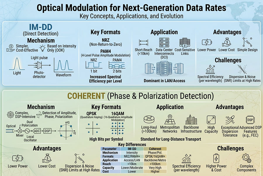
As mobile radio bandwidth increases, 50G optical interfaces provide a way to increase the capacity of an individual fronthaul connection without simply doubling the number of physical ports. 50G PAM4 modules can carry more data per optical symbol than conventional 25G NRZ interfaces, supporting higher per-channel throughput within a compatible system design.
50G fronthaul implementations include duplex and single-fiber bidirectional configurations. Different reach profiles and wavelength plans are available under relevant industry specifications. However, 50G optical modules are not automatically interchangeable with 25G modules, even when they use similar form factors.
Important 50G design factors include:
PAM4 modulation and receiver performance.
Supported line rate and host electrical interface.
Transmitter output power and receiver sensitivity.
FEC requirements and end-to-end compatibility.
Wavelength range and optical channel spacing.
Module power consumption and thermal characteristics.
Rate switching and diagnostic management support, where required.
Migration from 25G NRZ to 50G PAM4 requires a complete compatibility assessment. Data rate, optical power, receiver sensitivity, wavelength, electrical characteristics and link budget must all match the target system.
8. 100G Optical Modules for Mobile Aggregation and Transport
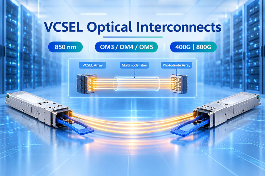
100G optical modules provide higher-capacity interfaces for aggregation switches, metro transport platforms and selected high-bandwidth radio transport architectures. QSFP28 is a widely used form factor for 100GbE connectivity, with different optical variants supporting multimode, parallel single-mode, duplex single-mode and WDM-based transmission.
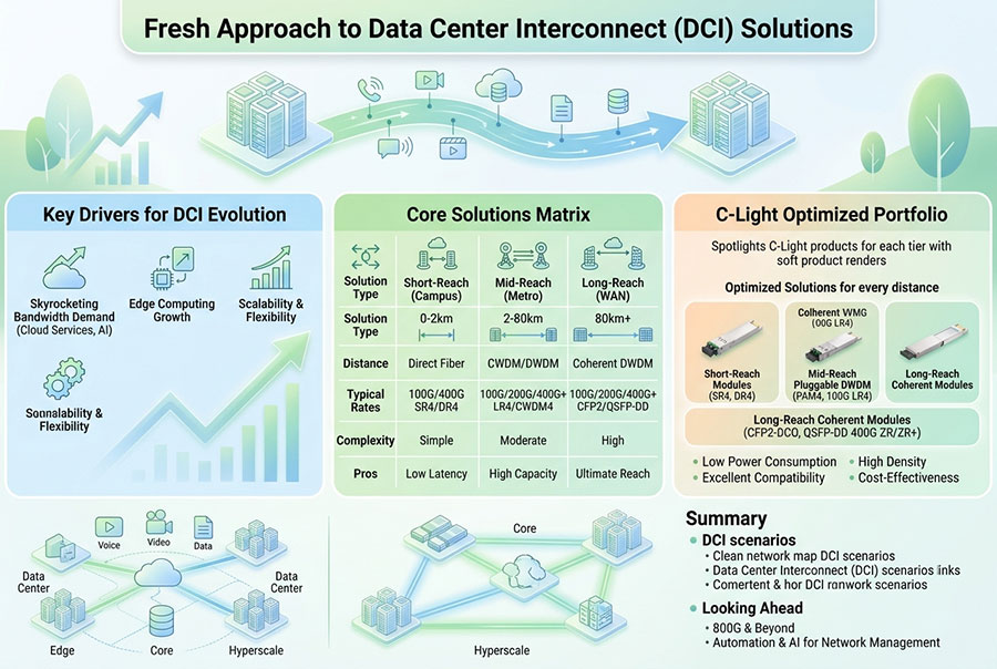
The appropriate 100G interface depends on the physical route and the network architecture. Shorter connections may use parallel-fiber SR4 or DR configurations, while longer single-mode routes may use CWDM4, LR4, ER4 or coherent optical solutions according to the required reach and system design.
| 100G Optical Category | Optical Architecture | Typical Network Role |
|---|---|---|
| SR4 | 850nm parallel multimode optics | Short equipment-room connections |
| DR | Parallel single-mode optics | Short single-mode links and aggregation connections |
| CWDM4 | Four wavelength channels over duplex single-mode fiber | 2km-class data and transport connections, subject to specification |
| LR4 | Four LAN-WDM wavelength channels | 10km-class single-mode transport links |
| ER4 | Four LAN-WDM wavelength channels with extended optical reach | Longer single-mode links where the optical budget permits |
| Coherent 100G | Coherent modulation and DSP-based transmission | Metro and longer-distance optical transport |
For backhaul networks with limited fiber resources, WDM and coherent optical interfaces can provide additional capacity over existing routes. The choice between direct-detect and coherent modules depends on transmission distance, channel plan, optical signal quality, line-system design and total system cost.
9. Coherent Optics and DWDM for Metro Backhaul
As mobile traffic converges into metro transport networks, higher-capacity optical links become important for connecting aggregation sites, regional facilities and mobile core locations. Coherent optical transceivers use advanced modulation and digital signal processing to improve spectral efficiency and support transmission over engineered optical paths.
DWDM systems carry multiple optical channels across a shared fiber pair or fiber route. Each channel occupies a defined wavelength or frequency slot, allowing network operators to increase total fiber capacity without installing a separate fiber pair for every service.
Coherent modules are available in different form factors and host interfaces, including CFP2, QSFP28, QSFP-DD and OSFP implementations. Their supported data rates and transmission distances vary by product design, modulation format, FEC implementation and optical line-system configuration.
Tunable coherent modules can simplify wavelength management by allowing a transceiver to operate on a selected channel within its supported tuning range. This is useful in DWDM networks where channel assignment and optical route planning are centrally managed.
For mobile backhaul, coherent optics are particularly relevant where traffic aggregation requires higher capacity over longer fiber routes. They should be engineered as part of a complete optical transport system, including amplifiers, multiplexers, dispersion characteristics and received optical performance.
10. Optical Budget and Transmission Reliability
Optical link engineering determines whether a selected transceiver can maintain a stable signal over the complete fiber route. The available optical power budget is calculated from the minimum transmitter output power and receiver sensitivity.
Available Optical Power Budget (dB) = Minimum Tx Output Power (dBm) − Receiver Sensitivity (dBm)
The calculated budget must accommodate fiber attenuation, connector loss, splice loss, patch panels, multiplexers and other passive components. An engineering margin is also required to account for installation variation, maintenance and future degradation.
| Optical Parameter | Engineering Impact | Verification Focus |
|---|---|---|
| Tx optical power | Determines the signal level launched into the fiber. | Minimum and maximum output power. |
| Rx sensitivity | Defines the minimum supported received signal level. | Sensitivity at the specified rate and BER. |
| Receiver overload | Limits excessive received optical power. | Maximum input power and attenuation requirements. |
| Fiber attenuation | Reduces received optical power over distance. | Wavelength-specific fiber loss. |
| WDM insertion loss | Consumes additional optical budget. | MUX/DEMUX loss and channel characteristics. |
| Connector and splice loss | Introduces additional loss along the route. | Connection quality and fiber testing. |
A module's nominal reach is based on defined test conditions. Real-world performance also depends on the quality of the installed fiber, connector cleanliness, optical reflections, route length and intermediate passive components. Longer links may require dispersion assessment, optical amplification or a different transmission technology.
11. Temperature, Power and Carrier-Grade Deployment
Mobile optical modules often operate in outdoor radio cabinets, remote shelters and distributed network facilities. These locations can experience wider temperature variations than controlled data center environments. Module selection must account for the actual operating temperature at the transceiver, not only the general ambient temperature reported for the site.
Extended-temperature optical modules are commonly specified for operating case-temperature ranges such as -40°C to +85°C, depending on the product. Commercial-temperature versions may be suitable for indoor aggregation facilities with controlled cooling. The exact limits must be confirmed from the module datasheet.
Carrier-grade deployment should consider:
Operating temperature range and thermal behavior under continuous load.
Power consumption and host equipment power limits.
Airflow around densely populated optical ports.
Laser operating stability over the specified temperature range.
Mechanical reliability and connector retention.
Long-term availability, replacement strategy and maintenance access.
DDM support for remote monitoring and fault identification.
Optical module reliability is especially important at remote radio sites, where equipment replacement may require scheduled field maintenance. Consistent specifications and validated compatibility can reduce operational complexity across large mobile deployments.
12. DDM Monitoring and Network Operations
Digital Diagnostic Monitoring provides operating information from supported optical transceivers. Network management systems can use this information to identify changes in optical performance and detect abnormal module conditions across distributed mobile transport sites.
Temperature: Monitors the internal operating temperature of the transceiver.
Supply voltage: Reports the module's electrical supply condition.
Laser bias current: Indicates transmitter laser operating conditions.
Tx optical power: Reports the transmitted optical power level.
Rx optical power: Helps identify changes in the received optical signal.
A gradual reduction in received optical power may indicate fiber degradation, connector contamination or changes in the optical path. Abnormal temperature or voltage readings may reveal environmental or host equipment issues.
DDM data should be interpreted alongside link alarms, interface error counters, BER measurements and physical fiber testing. The accuracy and alarm thresholds of diagnostic readings depend on the specific module design.
13. Compatibility Across Mobile Transport Equipment
Optical transceiver compatibility involves the host interface, protocol, optical specification and equipment management system. A module that fits mechanically may still be unsuitable if its electrical interface, data rate, coding or optical characteristics do not match the host platform.
Data rate: Verify the exact interface speed supported by the radio, switch or transport equipment.
Protocol: Distinguish between Ethernet, CPRI, eCPRI and other transport requirements.
Optical standard: Confirm SR, LR, BiDi, CWDM, LWDM, DWDM or coherent specifications.
Wavelength: Match the wavelength plan at both ends of the link.
Fiber interface: Check single-mode or multimode fiber, connector type and polarity.
Optical budget: Verify transmitter power, receiver sensitivity and overload limits.
Electrical interface: Confirm host lane rate, signaling requirements and supported module power.
Management: Check EEPROM identification, DDM support and host firmware compatibility.
Environmental rating: Match the module temperature range to the actual installation environment.
Multi-vendor mobile transport networks require particular attention to interoperability. Testing should include the actual host equipment, optical path and required operating mode rather than relying only on the module's nominal data rate or connector type.
14. C-LIGHT Optical Transceiver Solutions for Mobile Networks
C-LIGHT provides optical transceiver solutions across Ethernet and optical transport applications. Different module categories can support the connectivity requirements of access aggregation, mobile backhaul and higher-capacity transport networks.
25G SFP28 Optical Transceivers
Compact optical interfaces for 25G-class access and fronthaul connections. Module selection can be based on transmission distance, fiber type, wavelength and host interface requirements.
100G QSFP28 Optical Transceivers
High-capacity interfaces for aggregation and transport equipment. Different optical configurations address short-reach, single-mode and WDM-based network requirements.
DWDM DCO Optical Transceivers
Coherent optical solutions for high-capacity metro and long-distance transport. Tunable wavelength configurations and supported line rates depend on the selected module specification and optical system design.
Relevant product categories include the C-LIGHT Optical Transceiver Portfolio and DWDM DCO Optical Transceivers.
15. Optical Network Planning for Future Mobile Capacity
Mobile transport infrastructure must support more than the initial bandwidth requirement of a radio deployment. Traffic growth, additional radio sites, higher-capacity antenna configurations and future network upgrades can all increase the demand placed on existing fiber routes.
A scalable optical design should consider the number of available fiber cores, the capacity of each link, aggregation topology, protection paths and the possibility of introducing WDM or higher-rate interfaces. In fiber-constrained areas, BiDi and wavelength multiplexing can improve fiber utilization. In high-capacity metro networks, 100G and coherent DWDM interfaces can provide additional transport capacity.
The transition toward future mobile architectures will also increase the importance of higher-rate optical interfaces, advanced synchronization and more flexible optical transport. Network operators should evaluate each upgrade according to its application, required reach, optical budget and equipment compatibility rather than adopting a single transceiver type across every network layer.
16. Conclusion
High-speed optical modules are essential components of mobile fronthaul and backhaul networks. SFP28 and SFP56 interfaces support 25G and 50G-class connectivity for selected access and fronthaul applications, while QSFP28 and higher-density form factors provide greater bandwidth for aggregation and transport infrastructure.
Gray optics, BiDi, CWDM, LWDM and DWDM address different fiber availability and transmission requirements. The correct solution depends on link distance, traffic capacity, timing performance, wavelength planning, optical power budget and environmental conditions.
A well-engineered optical transport network combines suitable transceiver specifications with validated host compatibility, reliable fiber infrastructure and effective monitoring. These elements provide a scalable foundation for current 5G services and future mobile network capacity expansion.
Looking for high-speed optical modules for mobile fronthaul or backhaul networks?
Contact C-LIGHT for optical specifications, transmission options and compatibility support.
Contact C-LIGHT >

 >
 >
 >
 >
 >
 >
 >