TEL:+86 132 6656 7067


Optical transceivers provide the optical connectivity required by Ethernet switches, routers, servers, storage systems, and telecommunications equipment. They convert electrical signals into optical signals for transmission over fiber and convert received optical signals back into electrical signals at the destination.
Optical transceivers are available in multiple form factors, data rates, wavelengths, fiber interfaces, and transmission ranges. These characteristics determine whether a module is suitable for a short data center link, a campus network, a telecom access system, or a long-distance optical connection.
1. Optical Transceiver Classification
Optical transceivers can be classified by several technical characteristics. A single module belongs to multiple categories at the same time. For example, a 100G QSFP28 LR4 transceiver is defined by its data rate, form factor, optical interface, and transmission range.
| Classification | Common Types | What It Defines |
|---|---|---|
| Form factor | SFP, SFP+, SFP28, QSFP+, QSFP28, QSFP-DD, OSFP | Physical size, host interface, and port compatibility |
| Data rate | 1G, 10G, 25G, 40G, 100G, 200G, 400G, 800G and higher | Supported network bandwidth |
| Fiber type | Single-mode and multimode | Fiber compatibility and typical reach |
| Optical interface | SR, DR, FR, LR, ER, ZR | Optical design and target transmission distance |
| Wavelength | 850 nm, 1310 nm, 1550 nm and wavelength-specific variants | Optical transmission characteristics and fiber application |
| Transmission technology | Direct detection, coherent optics, CWDM, DWDM | Signal modulation, wavelength utilization, and system architecture |
2. Optical Transceiver Types by Form Factor
The form factor determines the module's physical interface and the type of port it can occupy. Selecting the correct form factor is a basic requirement for compatibility with network equipment.
SFP and SFP+
SFP modules commonly support 1G Ethernet, while SFP+ is widely used for 10G Ethernet. Both use a compact single-port design and are common in enterprise switches, access networks, and aggregation equipment.
SFP28
SFP28 is designed for 25G-class connectivity and is widely used in server access, data center leaf switches, and high-speed enterprise links. Compatibility with SFP or SFP+ host ports depends on the platform and operating mode.
QSFP+ and QSFP28
QSFP+ is commonly associated with 40G Ethernet, while QSFP28 is widely used for 100G Ethernet. Their multi-lane architecture supports high port density in switches and routers.
QSFP-DD and OSFP
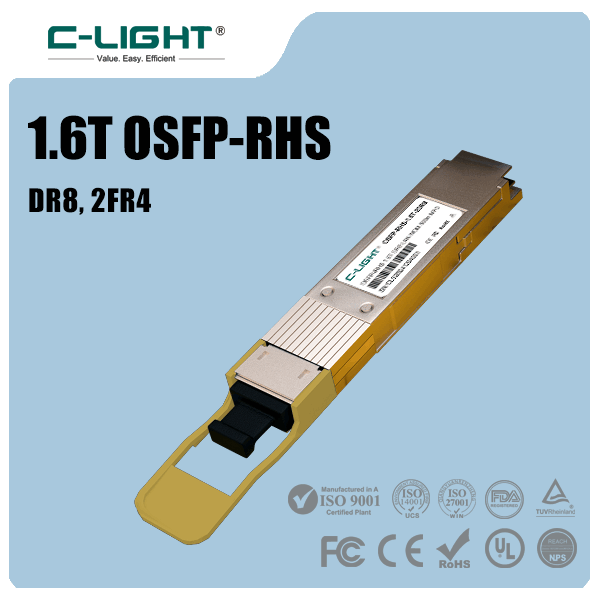
QSFP-DD and OSFP support high-speed applications including 400G and 800G, with supported rates depending on the module and host platform. They are commonly deployed in high-capacity data center and AI network infrastructure.
3. Optical Transceiver Types by Data Rate
Data rate selection depends on port capacity, server connectivity, switch architecture, and network traffic requirements. Higher-rate transceivers can increase bandwidth per port, but they also require compatible host interfaces, cabling, and link configurations.
| Data Rate | Common Form Factors | Typical Applications |
|---|---|---|
| 1G | SFP | Enterprise access, legacy Ethernet, and network management |
| 10G | SFP+ | Enterprise uplinks, storage networks, and server connections |
| 25G | SFP28 | Data center server access and leaf-switch connectivity |
| 40G | QSFP+ | Aggregation networks and legacy high-speed data center links |
| 100G | QSFP28 | Spine-leaf networks, core links, and high-capacity uplinks |
| 200G | QSFP56 and supported newer platforms | High-density switching and data center interconnects |
| 400G | QSFP-DD, OSFP | Cloud infrastructure, AI clusters, and high-capacity switching |
| 800G | QSFP-DD800, OSFP | High-performance computing and next-generation data center fabrics |
Form factors and data rates are not interchangeable labels. A module's supported rate must match the electrical interface, optical lane configuration, and host equipment capabilities. Some modules support multiple operating modes, while others are designed for a specific rate.
4. Single-Mode and Multimode Transceivers
Single-Mode Optical Transceivers
Single-mode transceivers operate over single-mode fiber (SMF), which has a small core designed to carry light with limited modal dispersion. Common wavelengths include 1310 nm and 1550 nm, although the exact wavelength depends on the optical interface.
Single-mode optics support a broad range of link distances, from short data center connections to campus links and long-distance transmission. Common interface families include DR, FR, LR, ER, and ZR, each associated with particular optical specifications and application ranges.
Multimode Optical Transceivers
Multimode transceivers operate over multimode fiber (MMF), commonly using 850 nm optics for short-reach data center applications. They are often used for rack-to-rack and equipment-room links where the installed fiber plant supports the required distance and bandwidth.
OM3, OM4, and OM5 are common multimode fiber categories. Supported reach varies with fiber grade, data rate, transceiver design, and the applicable standard. Higher-speed multimode links may require parallel optical lanes and multifiber connectors.
| Characteristic | Single-Mode Fiber | Multimode Fiber |
|---|---|---|
| Common wavelength | 1310 nm, 1550 nm, and other specified wavelengths | 850 nm for many short-reach Ethernet optics |
| Typical use | Data center, campus, telecom, and longer-distance links | Short-reach data center and equipment-room links |
| Fiber categories | OS1 and OS2 | OM3, OM4, and OM5 |
| Reach considerations | Depends on interface type, optical budget, and fiber route | Depends on fiber grade, data rate, and transceiver specification |
5. Optical Interfaces: SR, DR, FR, LR, ER, and ZR
Optical interface designations identify different transmission applications and are commonly associated with specified reach and fiber requirements. Exact distances depend on the applicable standard or multi-source agreement and the individual product specification.
| Interface | Typical Fiber | Representative Reach | Common Application |
|---|---|---|---|
| SR | Multimode fiber | Typically tens to 100s of meters, depending on rate and fiber grade | Short-reach data center links |
| DR | Single-mode fiber | Commonly 500 m for 400G DR4 and certain 100G DR implementations | Parallel single-mode connections |
| FR | Single-mode fiber | Commonly 2 km for 100G FR1 and 400G FR4 implementations | Duplex or wavelength-multiplexed links, depending on design |
| LR | Single-mode fiber | Commonly 10 km for applicable Ethernet interfaces | Longer data center and campus connections |
| ER | Single-mode fiber | Often 30–40 km for specified implementations | Extended-reach network links |
| ZR | Single-mode fiber | Often associated with 80 km-class coherent applications | Long-distance optical transport and data center interconnects |
These labels should not be treated as universal reach guarantees across all data rates. For example, 400G FR4 and 400G DR4 use different optical architectures and cabling arrangements even though both support 400G Ethernet.
6. Wavelength and Wavelength-Multiplexing Technologies
Wavelength determines the optical carrier used by a transceiver. It affects fiber compatibility, optical component design, and the way multiple signals can share a fiber pair or optical path.
850 nm: Commonly used by short-reach multimode transceivers.
1310 nm: Widely used by single-mode Ethernet optics, including various DR, FR, and LR designs.
1550 nm: Common in longer-reach and wavelength-division multiplexing systems, with implementation-specific exceptions.
CWDM: Uses coarser wavelength spacing to carry multiple optical channels over shared fiber infrastructure.
DWDM: Uses closely spaced wavelengths to support higher channel density in optical transport and data center interconnect applications.
Wavelength multiplexing can increase the capacity of existing fiber routes, but the transceiver wavelengths must match the optical system's channel plan. Fiber loss, dispersion, amplification, filtering, and total optical power must also be considered in engineered links.
7. Direct-Detection and Coherent Transceivers
Optical transceivers also differ in how they encode and recover transmitted data. Direct-detection modules are widely used in Ethernet links across data centers and enterprise networks. Coherent transceivers use more advanced modulation and digital signal processing to recover optical amplitude and phase information, enabling high-capacity transmission over longer distances.
| Characteristic | Direct Detection | Coherent Optics |
|---|---|---|
| Common application | Data center Ethernet and many enterprise links | Metro, long-haul, and high-capacity DCI |
| Signal processing | Typically simpler receiver architecture | Advanced digital signal processing for amplitude and phase recovery |
| Distance and capacity | Depends on interface, lane rate, modulation, and optical budget | Supports high-capacity links over longer distances, depending on modulation and system design |
| Deployment factors | Host compatibility, fiber, connector, and FEC requirements | Wavelength plan, line system, baud rate, modulation, power, and host support |
8. How to Select the Right Optical Transceiver
Choosing a suitable transceiver requires more than matching the nominal data rate. The following checks help ensure that the module fits the network design and operates reliably.
Equipment compatibility: Confirm the switch or router model, port form factor, supported module list, and firmware requirements.
Data rate: Match the module to the required Ethernet or transport interface and the host's supported operating modes.
Transmission distance: Choose an optical interface that supports the complete route, including patch panels and intermediate connections.
Fiber and connector: Check SMF or MMF type, fiber grade, LC or MPO/MTP interface, polarity, and cabling arrangement.
Optical budget: Verify transmit power, receiver sensitivity, insertion loss, and any required engineering margin.
Power and temperature: Ensure the module's power consumption and operating temperature meet the host platform's limits.
Network configuration: Confirm lane mapping, breakout support, FEC settings, wavelength compatibility, and link mode.
Testing: Validate module recognition, optical diagnostics, link stability, and error performance in the intended equipment.
9. Frequently Asked Questions
Common categories include SFP, SFP+, SFP28, QSFP+, QSFP28, QSFP-DD, and OSFP by form factor; SR, DR, FR, LR, ER, and ZR by optical interface; and single-mode or multimode by fiber type.
Single-mode transceivers operate over single-mode fiber and support a broad range of distances. Multimode transceivers are commonly used for shorter links over multimode fiber. The appropriate choice depends on the interface specification and installed fiber infrastructure.
They can interoperate when both modules meet the same applicable interface specification and are supported by the host equipment. Vendor coding, firmware, optical specifications, and configuration may affect compatibility.
No. Data rate and reach are separate characteristics. A short-reach 400G module may support less distance than a lower-rate long-reach module. Reach is determined by optical design, fiber type, signal characteristics, and link budget.
Provide the equipment brand and model, port type, required data rate, transmission distance, fiber type, connector, and existing module part number if available. These details help narrow down compatible options.
10. Conclusion
Optical transceiver types are defined by several interrelated factors, including form factor, data rate, fiber interface, wavelength, transmission reach, and signal-processing technology. Understanding these categories helps network engineers select modules that match the physical infrastructure and performance requirements of each link.
For data centers, enterprise networks, and telecom systems, reliable optical connectivity depends on accurate specification matching and equipment compatibility. Checking the host port, fiber route, optical budget, power requirements, and supported network configuration before deployment helps reduce integration issues and maintain stable link performance.
Optical Transceiver Solutions
Looking for optical transceivers for data center, enterprise, or telecom applications? Prepare your equipment model, data rate, link distance, and fiber requirements to identify a suitable module.
Contact C-LIGHT >

 >
 >
 >
 >
 >
 >
 >