TEL:+86 132 6656 7067


400G optical modules provide high-bandwidth connectivity for modern data center networks, connecting switches, routers, servers, and high-performance computing infrastructure. As network traffic increases with cloud services, distributed storage, and AI workloads, 400G Ethernet links help improve port capacity while supporting scalable network architectures.
Available in multiple form factors, optical interfaces, and transmission distances, 400G transceivers can support both short-reach connections within a data center and longer links between network facilities. Selecting the right module requires consideration of switch compatibility, fiber type, link distance, power consumption, and the intended Ethernet architecture.
1. What Is a 400G Optical Module?
A 400G optical module is a pluggable transceiver designed to transmit and receive data at a nominal aggregate rate of 400 gigabits per second. It converts electrical signals from network equipment into optical signals for transmission over fiber, then converts received optical signals back into electrical signals.
Most 400G Ethernet transceivers use multiple optical or electrical lanes to achieve the aggregate data rate. Depending on the design, a module may use parallel fibers, wavelength multiplexing over duplex fiber, or different optical modulation and signal-processing technologies.
Common applications include:
Data center spine-leaf switching and high-capacity Ethernet uplinks.
Cloud computing, virtualization, and distributed storage networks.
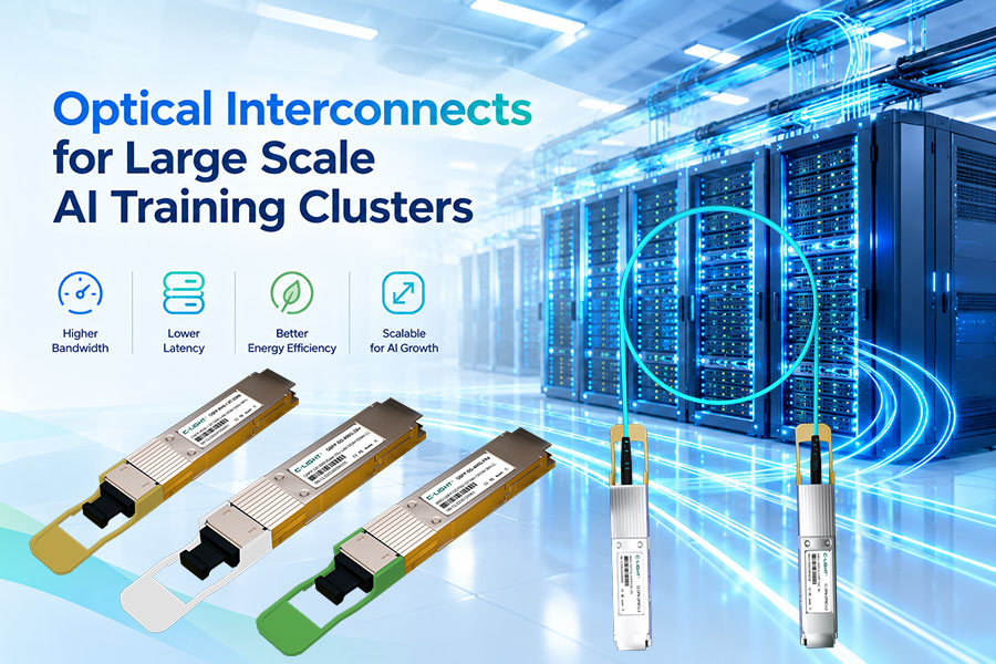
AI clusters and high-performance computing fabrics.
Data center interconnects and links between network rooms or facilities.
Enterprise and service-provider networks requiring 400G Ethernet connectivity.
2. Common 400G Optical Module Form Factors
400G QSFP-DD
QSFP-DD uses a double-density electrical interface to provide 400G connectivity in a compact form factor. It is widely used in switches and routers designed for high port density.
Typical product options include SR8, DR4, FR4, and selected extended-reach variants, depending on the platform and application.
400G OSFP
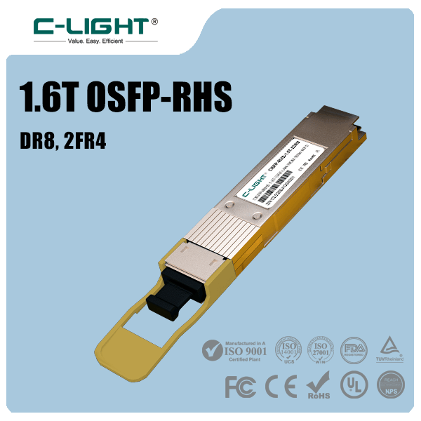
OSFP is another form factor designed for high-speed networking. Its mechanical design and thermal characteristics support deployments that require substantial bandwidth and power capacity per port.
OSFP modules are commonly considered for high-performance switches and AI infrastructure, subject to the equipment's supported port type.
QSFP-DD and OSFP modules are not mechanically interchangeable. Before ordering, verify the host port, module form factor, thermal requirements, firmware support, and the equipment manufacturer's compatibility guidance.
3. Major 400G Optical Module Types
| Module Type | Optical Interface | Typical Fiber | Common Reach | Typical Application |
|---|---|---|---|---|
| 400G SR8 | Parallel multimode optics | Multimode fiber (MMF) | Up to 100 m on supported OM4 links | Short-reach data center connections |
| 400G DR4 | Parallel single-mode optics | Single-mode fiber (SMF) | Up to 500 m | Switch-to-switch and breakout links |
| 400G FR4 | Four wavelengths over duplex fiber | Single-mode fiber (SMF) | Up to 2 km | Duplex-fiber data center links |
| 400G LR4 | Wavelength-multiplexed optics | Single-mode fiber (SMF) | Up to 10 km for applicable implementations | Longer-reach campus or data center links |
4. 400G SR8, DR4, and FR4: Key Differences
400G SR8 for Short-Reach Multimode Links
400G SR8 is designed for short-distance transmission over multimode fiber. Parallel optical lanes provide the aggregate bandwidth, making SR8 suitable for connections where multimode infrastructure is already available and link distances remain within the supported optical budget.
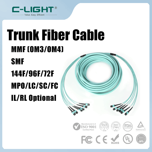
SR8 implementations commonly use MPO/MTP-style multifiber connectivity. Polarity, fiber count, connector gender, and the optical lane arrangement must match the module and cabling design.
400G DR4 for Single-Mode Fiber
400G DR4 uses parallel single-mode optical lanes and is commonly specified for links up to 500 meters. Its optical architecture can also support breakout configurations when paired with compatible host ports and remote transceivers.
For example, a 400G DR4 port may be deployed in a 4 × 100G breakout arrangement using compatible 100G DR optical interfaces. The precise configuration depends on the module's lane mapping, switch support, and cabling.
400G FR4 for Duplex-Fiber Connectivity
400G FR4 uses wavelength multiplexing to carry multiple optical channels over a duplex single-mode fiber connection. This reduces the fiber count compared with parallel-fiber interfaces and is useful where LC duplex cabling is preferred.
FR4 is commonly used for links up to 2 km. It is often a practical choice for data center connections that require more reach than short-reach multimode optics while retaining a duplex-fiber interface.
5. Fiber and Connector Selection
The optical interface determines which fiber and cabling assembly the network requires. Choosing the wrong fiber type or connector can prevent a link from operating correctly, even when both transceivers support 400G Ethernet.
| Consideration | Parallel-Fiber Modules | Duplex-Fiber Modules |
|---|---|---|
| Fiber type | MMF for SR8; SMF for DR4 and other parallel single-mode designs | Generally SMF for FR4 and LR4 implementations |
| Common connector | MPO/MTP-style multifiber connector, depending on the module | LC duplex for common FR4 and LR4 implementations |
| Fiber count | Multiple fibers for transmit and receive lanes | Two fibers for transmit and receive |
| Primary planning factor | Fiber polarity, lane mapping, and connector configuration | Wavelength compatibility, duplex polarity, and optical budget |
For existing fiber infrastructure, check the installed fiber grade, route length, patch panels, connector cleanliness, and insertion loss. The cabling system must meet the selected optical interface's requirements across the complete link.
6. 400G Breakout Connectivity
Some 400G optical modules and host ports support breakout operation, allowing one high-speed port to connect to multiple lower-speed interfaces. This can simplify migration from 100G links to a 400G switching platform or provide flexible connectivity for server and leaf-switch networks.
| Configuration | Potential Use | Verification Required |
|---|---|---|
| 400G to 4 × 100G | Connecting a 400G switch port to four 100G interfaces | Host breakout support, lane mapping, remote optics, and cable compatibility |
| 400G to 2 × 200G | Connecting to two 200G interfaces where supported | Module design, switch operating mode, and remote interface support |
Breakout capability is not determined by data rate alone. Confirm that the switch supports the intended breakout mode and that the selected optical module or cable assembly provides the required lane mapping. A 400G module cannot be assumed to support every lower-speed combination.
7. Power Consumption, Thermal Design, and Compatibility
400G transceivers typically require more power and generate more heat than lower-speed modules. Thermal performance becomes especially important in high-density switches, where multiple adjacent ports may operate simultaneously under sustained traffic.
Power budget: Confirm that the host port can supply the module's specified maximum power.
Cooling: Check airflow direction, heatsink design, inlet temperature, and the platform's thermal limits.
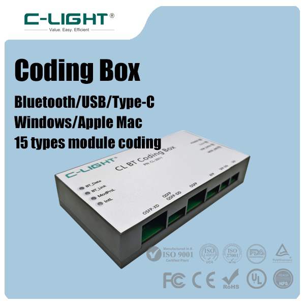
Firmware and coding: Verify module recognition, supported operating modes, and any vendor-specific restrictions.
Link configuration: Match Ethernet speed, FEC requirements, lane settings, and remote transceiver specifications.
Optical performance: Check transmit power, receiver sensitivity, optical budget, and supported link length.
For multi-vendor networks, physical fit alone does not guarantee interoperability. The module must meet the applicable interface specification and operate correctly with the switch or router's software, firmware, and configuration.
8. How to Choose the Right 400G Optical Module
Use the following factors to narrow down the appropriate module for a data center deployment:
Host equipment: Identify the switch or router model and confirm whether it supports QSFP-DD or OSFP.
Transmission distance: Select the optical reach based on the actual fiber route, patch panels, and expected link loss.
Fiber infrastructure: Choose SR8 for suitable short-reach multimode links, or a compatible single-mode option for DR4, FR4, or LR4 applications.
Connector requirements: Verify MPO/MTP or LC duplex connectivity, fiber polarity, and the required cabling assembly.
Network architecture: Determine whether the link requires native 400G connectivity or a supported breakout configuration.
Operating conditions: Check power consumption, cooling, temperature range, and the equipment's module support list.
Deployment testing: Validate interoperability and link performance in the target platform before large-scale rollout.
9. Frequently Asked Questions
They are different transceiver form factors with distinct mechanical and thermal designs. The correct choice depends on the host equipment's port type, supported modules, power limits, and cooling requirements.
Reach depends on the module type. Common examples include up to 100 m for SR8 on supported OM4 fiber, 500 m for DR4, 2 km for FR4, and 10 km for applicable LR4 implementations. Always confirm the specific product specification.
Some 400G modules and switch ports support 4 × 100G breakout. Compatibility depends on the optical interface, lane mapping, remote modules, cabling, and switch configuration.
No. SR8 is a common multimode option for short-reach links, while DR4, FR4, and LR4 implementations use single-mode fiber. Fiber type must match the selected transceiver.
Confirm the equipment model, form factor, Ethernet interface, link distance, fiber type, connector, breakout requirements, power consumption, and vendor compatibility. Requesting the module datasheet before purchase helps prevent deployment mismatches.
10. Conclusion
400G optical modules support high-capacity data center networks with a range of form factors, optical interfaces, and transmission distances. QSFP-DD and OSFP address different host-port designs, while SR8, DR4, FR4, and LR4 serve different fiber and reach requirements.
Reliable deployment depends on matching the transceiver to the equipment, fiber infrastructure, link budget, and network configuration. Careful compatibility checks and pre-deployment testing help reduce integration issues and support stable 400G connectivity for cloud, enterprise, and AI data center environments.
400G Optical Connectivity Solutions
Need help selecting 400G optical modules for your switches, routers, or data center links? Confirm your equipment model, required distance, fiber type, and interface to identify a suitable configuration.
Contact C-LIGHT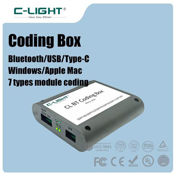 >
>

 >
>
 >
>
 >
>
 >
>
 >
>
 >
>
 >
>