TEL:+86 132 6656 7067


The growing bandwidth requirements of AI data centers, high-performance computing systems, and large-scale cloud networks are driving the development of 1.6T optical connectivity. As network capacity increases, simply adding more transmission lanes becomes increasingly difficult because of limitations in switch port density, electrical routing, power consumption, and optical packaging.
200G per lane technology addresses these challenges by increasing the data rate carried by each electrical and optical channel. A common 1.6T architecture combines eight 200G-class lanes to deliver 1.6 Tbps of aggregate bandwidth. This approach increases the capacity of individual connections while reducing the number of lanes required compared with earlier 100G-per-lane designs.
The transition to 200G per lane requires advances in PAM4 signaling, high-speed SerDes, DSP, optical transmitters and receivers, and signal integrity engineering. These technologies work together to make 1.6T connectivity practical for next-generation data center networks.
1. What Is 200G Per Lane Technology?
200G per lane technology refers to a high-speed transmission architecture in which each individual data lane carries a nominal data rate of approximately 200 Gbps. Multiple lanes are combined to achieve the aggregate bandwidth of an optical module or network interface.
In a typical 1.6T client-optics architecture, eight lanes each carry approximately 200 Gbps:
8 lanes × 200 Gbps = 1,600 Gbps = 1.6 Tbps
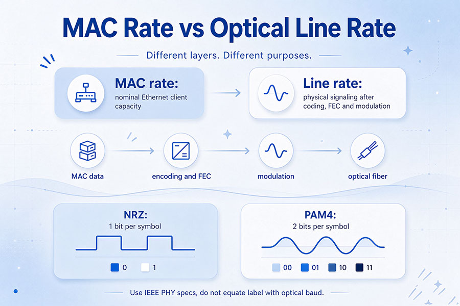
Each lane uses PAM4 signaling, which represents two bits per symbol through four distinct signal levels. This allows a higher bit rate without requiring a separate electrical or optical channel for every individual bit.
The term 200G per lane describes the nominal data capacity of an individual lane. It should not be confused with the symbol rate, raw line rate, or total bandwidth of the complete module.
1.1 200G Data Rate and PAM4 Symbol Rate
PAM4 encodes two bits in each symbol. Therefore, a nominal 200 Gbps lane requires a symbol rate of approximately 100 GBd before accounting for the details of coding and error-correction overhead.
A representative 200G PAM4 interface operates at approximately 106.25 GBd, corresponding to a 212.5 Gb/s signaling rate. The exact rate depends on the interface specification and its coding and FEC arrangement.
This distinction is important when evaluating 200G electrical interfaces and optical modules. A lane described as 200G does not necessarily operate at exactly 200 GBd or carry only 200 Gb/s of raw signaling.
1.2 From 100G Per Lane to 200G Per Lane
The transition from 100G to 200G per lane doubles the nominal data capacity of each channel. Earlier 100G-per-lane PAM4 interfaces commonly use a symbol rate around 53.125 GBd, while 200G-per-lane designs move toward approximately 106.25 GBd.
| Parameter | 100G Per Lane | 200G Per Lane |
|---|---|---|
| Nominal Lane Rate | 100 Gbps | 200 Gbps |
| Modulation | PAM4 | PAM4 |
| Representative Symbol Rate | 53.125 GBd | 106.25 GBd |
| Bits Per Symbol | 2 | 2 |
| Typical Application | 400G and 800G architectures | 800G and 1.6T architectures |
The main change is not a new modulation format. It is the ability to operate PAM4 signaling at a substantially higher symbol rate while maintaining the required signal quality and error performance.
2. How 200G Per Lane Enables 1.6T Networks
1.6T network interfaces can be built by combining multiple high-speed lanes. The 200G-per-lane approach provides a straightforward path to 1.6 Tbps using eight lanes.
2.1 The 8 × 200G Architecture
A common 1.6T optical transceiver architecture uses eight electrical lanes on the host side and eight corresponding optical lanes on the line side. Each lane carries a nominal 200G data rate.
Host electrical interface: 8 × 200G
Optical transmission interface: 8 × 200G-class lanes
Aggregate module bandwidth: 1.6 Tbps
This architecture can support parallel optical transmission or other optical arrangements depending on the module design. The electrical and optical lane mapping is implementation-dependent, so not every 1.6T transceiver uses identical internal signal routing.
2.2 200G Per Lane in 800G Networks
200G per lane technology is also relevant to 800G connectivity. Four 200G-class lanes can provide an aggregate bandwidth of 800 Gbps.
This allows 800G and 1.6T interfaces to share a common lane-rate generation while using different lane counts. It can simplify the development of related electrical interfaces, optical components, and signal-processing platforms.
2.3 200G Per Lane Compared with 16 × 100G
Eight 200G lanes are not the only way to achieve 1.6T. Another architecture uses sixteen 100G lanes:
8 × 200G: Eight high-speed lanes provide 1.6 Tbps.
16 × 100G: Sixteen lower-rate lanes also provide 1.6 Tbps.
The choice affects electrical interface design, connector requirements, optical mapping, module packaging, power distribution, and host platform compatibility. For example, 1.6T OSFP-RHS and OSFP-XD implementations may use different lane configurations and mechanical or electrical design approaches.
| Architecture | Lane Configuration | Aggregate Bandwidth | Main Design Consideration |
|---|---|---|---|
| 800G, 100G per lane | 8 × 100G | 800 Gbps | Established 100G-class lane architecture |
| 800G, 200G per lane | 4 × 200G | 800 Gbps | Higher per-lane signaling rate |
| 1.6T, 100G per lane | 16 × 100G | 1.6 Tbps | Higher lane count and denser interfaces |
| 1.6T, 200G per lane | 8 × 200G | 1.6 Tbps | Higher speed per lane with fewer lanes |
The 8 × 200G architecture is an important direction for 1.6T client optics, but actual module selection must follow the host platform's supported form factor and interface configuration.
3. The Role of PAM4 in 200G Per Lane Transmission
PAM4 is central to 200G-per-lane transmission because it carries two bits per symbol. Compared with a two-level NRZ signal, PAM4 doubles the number of bits represented by each symbol at the same symbol rate.
3.1 Four-Level Signal Encoding
A PAM4 signal uses four amplitude levels to represent four possible symbol states. Each symbol represents one of four two-bit combinations: 00, 01, 10, or 11.
This signaling method increases the amount of information carried per symbol without requiring the same proportional increase in symbol frequency that would be needed with NRZ.
3.2 Higher Symbol Rates and Signal Quality
Although PAM4 improves spectral efficiency, moving to approximately 106.25 GBd creates demanding signal-integrity requirements. The receiver must distinguish four amplitude levels despite noise, attenuation, reflections, crosstalk, and timing variation.
The vertical separation between adjacent PAM4 levels is smaller than the full signal swing of a two-level NRZ signal. This makes high-speed PAM4 links more sensitive to noise and distortion.
3.3 Forward Error Correction
Forward error correction (FEC) is essential to high-speed PAM4 communication. It adds controlled redundancy to transmitted data so that the receiver can detect and correct a certain number of errors.
FEC requirements depend on the applicable interface and transmission design. The host and optical module must support compatible error-correction behavior. Some optical applications may also introduce additional coding within the module, affecting the optical line rate.
FEC improves link reliability, but it does not eliminate the need for good electrical channel design, optical performance, and receiver sensitivity.
4. 224G SerDes: The Electrical Foundation of 200G Per Lane
The move to 200G per lane requires a corresponding increase in the speed of electrical interfaces between the switch ASIC and optical subsystem. This generation is commonly associated with 224G-class SerDes technology.
SerDes, short for serializer/deserializer, converts parallel data into high-speed serial signals for transmission and converts received serial signals back into parallel data.
4.1 Why 224G SerDes Matters
Traditional 112G-class electrical interfaces support the 100G-per-lane generation. The next generation of approximately 224G-class SerDes supports the higher signaling rates needed for nominal 200G-per-lane transmission.
The term 224G refers to an interface generation or signaling class. It should not be interpreted as meaning that the useful payload rate of every lane is exactly 224 Gbps.
4.2 Electrical Channel Challenges
At higher signaling rates, electrical channels become more sensitive to frequency-dependent insertion loss, return loss, crosstalk, and reflections. PCB traces, connectors, package substrates, and module contacts all contribute to the overall channel response.
Designers must optimize the complete electrical path rather than evaluating the SerDes chip in isolation.
4.3 Equalization and Signal Processing
High-speed SerDes systems use signal-processing techniques to compensate for channel impairments. Depending on the implementation, these may include transmitter equalization, receiver equalization, clock recovery, and digital signal processing.
These functions help preserve signal quality across the host electrical interface and support reliable operation at 200G per lane.
5. The Role of DSP in 1.6T Optical Transceivers
Digital signal processors play an important role in many 1.6T optical transceiver designs. As lane rates increase, the transmitter and receiver must manage more demanding electrical and optical signal conditions.
5.1 Transmitter Signal Conditioning
The DSP and associated driver circuitry prepare electrical signals for the optical transmitter. Depending on the architecture, functions may include equalization, signal shaping, lane mapping, and other transmitter-side processing.
5.2 Receiver Signal Processing
On the receiving side, the optical signal is converted into an electrical signal by photodetectors and receiver circuitry. DSP functions can help compensate for signal impairments and support reliable data recovery.
5.3 Retimed and Linear Architectures
Different optical architectures distribute signal-processing functions differently.
Retimed optics: Use active signal-processing circuitry, such as a DSP or retimer, to condition or recover high-speed signals.
Linear Pluggable Optics (LPO): Reduce or remove certain retiming functions in the module and rely more heavily on the host system's electrical interface and signal processing.
Linear Receive Optics (LRO): Use a linear approach on the transmit side while retaining selected receiver-side processing, depending on the implementation.
These architectures involve different trade-offs in power, signal integrity, reach, host requirements, and interoperability. A 200G-per-lane interface does not automatically require one specific DSP architecture.
For a more detailed discussion, see DSP in 1.6T Optical Transceivers.
6. Optical Components Supporting 200G Per Lane
Increasing the electrical lane rate is only one part of building a 1.6T optical interface. Optical transmitters, modulators, photodetectors, receivers, and fiber connections must also support the required data rate and transmission distance.
6.1 Optical Transmitters
The transmitter converts high-speed electrical data into modulated optical signals. Depending on the optical design, it may use directly modulated lasers, electro-absorption modulated lasers, or an external laser combined with a separate modulator.
The appropriate transmitter technology depends on the target reach, wavelength, optical power budget, modulation performance, and thermal requirements.
6.2 Optical Modulators
Optical modulators encode electrical data onto light. At 200G per lane, modulator bandwidth, linearity, insertion loss, and drive requirements become important design factors.
Silicon photonics and other photonic integration technologies can help combine multiple optical functions into compact assemblies, although the actual implementation varies between products.
6.3 Photodetectors and Receiver Circuits
At the receiving end, photodetectors convert incoming optical signals into electrical current. Transimpedance amplifiers (TIAs) amplify the resulting signals so that subsequent receiver circuits can process them.
Receiver sensitivity, bandwidth, noise performance, and optical coupling all affect the reliability of a 200G optical lane.
6.4 Fiber and Optical Interface Design
High-speed optical modules must also provide suitable fiber interfaces. Parallel optics may use multiple fiber channels, while wavelength-division multiplexing architectures can combine multiple optical channels onto fewer fiber paths.
Connector selection, fiber type, insertion loss, optical return loss, and channel mapping must match the intended application.
7. 200G Per Lane and 1.6T Optical Module Architectures
1.6T optical transceivers combine high-speed electrical interfaces with optical transmission and reception components. Their internal architecture determines how host signals are processed and mapped to optical channels.
7.1 1.6T OSFP-RHS
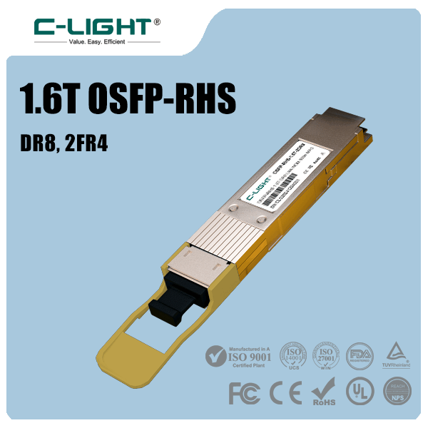
OSFP-RHS is one form-factor approach for high-density 1.6T optical connectivity. In an eight-lane 200G-class implementation, the module supports an aggregate bandwidth of 1.6 Tbps.
Depending on the optical variant, 1.6T modules may support different reach and fiber configurations. For example, DR8 and 2×FR4 represent different optical channel arrangements and should not be treated as the same optical interface.
C-LIGHT's 1.6T OSFP-RHS optical module is relevant to this next-generation connectivity category. Product selection should be based on the exact optical variant, reach, host interface, and supported application.
7.2 DR8 Optical Configuration
DR8 is a parallel single-mode optical architecture that uses eight optical lanes. In a 1.6T 200G-per-lane implementation, the eight lanes collectively provide 1.6 Tbps of aggregate bandwidth.
DR8 designs are intended for specific single-mode fiber applications and transmission distances. The optical budget, fiber plant, connector configuration, and host compatibility must be checked for each module.
7.3 2×FR4 Optical Configuration
FR4 uses wavelength-division multiplexing to carry multiple optical channels over a fiber pair. A 2×FR4 arrangement provides two independent FR4 optical interfaces, allowing the module to support two separate 800G-class optical connections where the host and module design support that operating mode.
This architecture differs from a parallel DR8 configuration in its wavelength arrangement, fiber interface, and optical channel mapping.
8. Key Engineering Challenges of 200G Per Lane
Moving from 100G to 200G per lane introduces several engineering challenges across electrical design, optical performance, thermal management, and manufacturing.
8.1 Signal Integrity
Higher symbol rates increase sensitivity to channel loss, reflections, crosstalk, and timing distortion. PCB materials, trace geometry, connectors, package design, and electrical interfaces must be carefully controlled.
8.2 Power Consumption
Higher-speed SerDes, DSP, laser drivers, TIAs, and optical components can increase power demands. Improving power efficiency requires optimization across the complete transceiver rather than focusing on one component.
8.3 Thermal Management
High-density 1.6T modules must operate within the thermal limits of the host system. Heat generated by the DSP, drivers, laser sources, and receiver electronics can affect module performance and reliability.
Heat sinks, airflow, module placement, and host cooling capacity must be considered during system design.
8.4 Optical Performance and Link Budget
Higher optical lane rates place greater demands on transmitter quality, receiver sensitivity, and signal integrity. Designers must account for transmitter and dispersion eye closure, optical modulation amplitude, receiver noise, fiber attenuation, and connector losses as applicable to the interface.
8.5 Testing and Interoperability
Testing must cover both electrical and optical performance. Important checks include lane mapping, signal quality, bit error rate, FEC behavior, optical power, temperature, and compatibility with the host platform.
A module that meets an individual component specification may still require system-level validation before deployment. The host ASIC, firmware, electrical interface, optical link, and management functions must operate together correctly.
9. Why 200G Per Lane Matters for AI Data Centers
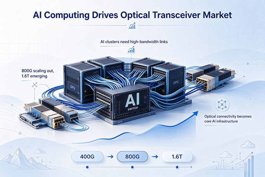
AI training and inference systems depend on fast communication between GPUs, accelerators, switches, and storage infrastructure. As clusters grow, the network must handle increasing traffic volumes while maintaining predictable latency and reliable data delivery.
9.1 Higher Bandwidth per Port
By increasing the capacity of each lane, 200G technology enables higher aggregate bandwidth without proportionally increasing the number of lanes. This is valuable for switch platforms that need to support more traffic within limited front-panel and package space.
9.2 Higher-Density Network Fabrics
Eight 200G lanes provide 1.6T of aggregate capacity. This can help data center operators increase port bandwidth and build higher-capacity network fabrics while managing the physical constraints of switches, cables, and optical modules.
9.3 Support for Next-Generation Switch Platforms
Higher-capacity switch ASICs require optical interfaces capable of matching their aggregate bandwidth. 200G-per-lane electrical and optical technologies provide an important building block for 1.6T interfaces and future network generations.
9.4 A Foundation for Future Optical Integration
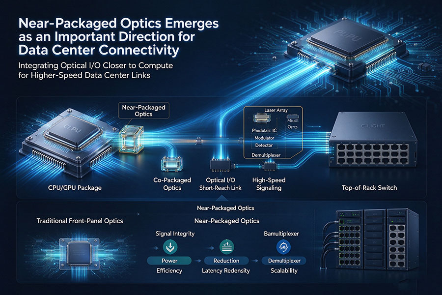
As per-lane data rates increase, the electrical distance between the host ASIC and optical conversion components becomes more important. This creates additional interest in near-packaged optics (NPO), co-packaged optics (CPO), and advanced optical I/O architectures.
200G per lane is therefore relevant not only to pluggable transceivers but also to the broader evolution of high-density optical connectivity.
10. 200G Per Lane and the Future of 1.6T Networks
The development of 200G-per-lane technology is an important step toward higher-capacity Ethernet and optical interconnect systems. It allows 1.6T interfaces to use eight high-speed lanes rather than relying exclusively on a larger number of lower-rate channels.
Future improvements will depend on several technology areas:
Advanced SerDes: Higher-speed electrical interfaces with improved signal integrity and power efficiency.
Improved PAM4 DSP: More effective equalization, signal recovery, and diagnostics for high-speed lanes.
Advanced optical components: Faster modulators, laser sources, photodetectors, and receiver circuits.
Silicon photonics: Greater photonic integration and compact optical engine designs.
Advanced packaging: Better electrical and optical interconnects for high-density modules and integrated systems.
New network architectures: Wider adoption of 1.6T connectivity across AI clusters and high-performance data center networks.
Standardization and interoperability will also remain important. IEEE Ethernet interface specifications and relevant industry agreements help define electrical and optical requirements, while manufacturers must validate their products against actual host platforms and deployment conditions.
Conclusion
200G per lane technology is a major building block for 1.6T network connectivity. By carrying approximately 200 Gbps on each lane using high-speed PAM4 signaling, an eight-lane architecture can deliver an aggregate bandwidth of 1.6 Tbps.
Achieving this performance requires more than doubling the lane rate. High-speed SerDes, DSP, optical transmitters, photodetectors, FEC, thermal management, and advanced packaging must work together to maintain signal quality and reliable operation.
As AI data centers and high-capacity switching platforms continue to expand, 200G-per-lane technology will support the transition toward denser optical interfaces and more integrated network architectures. It provides an important foundation for current 1.6T systems and the next stage of high-speed optical connectivity.
 >

 >
 >
 >
 >
 >
 >
 >