TEL:+86 132 6656 7067


Ethernet bandwidth and optical transmission speed are closely related, but they describe different aspects of a network connection. An Ethernet interface processes data at the Media Access Control (MAC) layer, while the optical transceiver converts electrical signals into optical signals for transmission across fiber. Between these two functions, physical-layer encoding, modulation, framing, and forward error correction can affect the total signaling rate required on the optical link.
This distinction becomes increasingly important in 100G, 400G, 800G, and 1.6T networks. A transceiver's optical line rate may be higher than its Ethernet MAC rate because the physical layer must carry additional information beyond the Ethernet client data itself. Understanding this relationship helps network engineers evaluate transceiver specifications, port bandwidth, lane configurations, and interoperability.
1. What Is Ethernet MAC Rate?
Ethernet MAC rate refers to the nominal data rate supported by the Ethernet Media Access Control layer. The MAC layer handles Ethernet frame transmission and reception, including frame addressing, frame boundaries, and error detection through the Frame Check Sequence (FCS).
Common Ethernet MAC rates include 10G, 25G, 50G, 100G, 200G, 400G, 800G, and 1.6T. These rates describe the Ethernet interface capacity rather than the complete electrical or optical signaling rate required to transport the data.
For example, a 400GbE interface provides a nominal MAC data rate of 400 Gb/s. This does not necessarily mean that the optical transmitter sends exactly 400 billion binary signaling units per second. The PHY may use multiple lanes, modulation, coding, and FEC to support the required Ethernet bandwidth.
2. What Is Optical Line Rate?
Optical line rate describes the signaling rate used by the optical transmission system to transport information over fiber. It is determined by the physical-layer implementation, including the number of optical lanes, modulation format, symbol rate, and transmission coding.
In practical optical networking, several related terms are important:
Bit rate: The number of transmitted bits per second.
Symbol rate: The number of modulation symbols transmitted per second, measured in baud.
Lane rate: The signaling or data rate assigned to an individual electrical or optical lane.
Aggregate line rate: The combined transmission rate across all lanes.
These values are not interchangeable. For example, PAM4 transmits two bits per symbol, so its bit rate is twice its symbol rate before considering the details of coding and FEC.
3. Why Ethernet MAC Rate and Optical Line Rate Differ
The optical line rate may exceed the Ethernet MAC rate because physical-layer transmission includes functions that are not part of the MAC payload. These functions allow the receiver to recover clock timing, identify data boundaries, maintain signal integrity, and correct transmission errors.
Physical-Layer Encoding
Encoding transforms data into a format suitable for physical transmission. Depending on the Ethernet PHY architecture, encoding may introduce redundancy or additional signaling requirements.
For example, 64b/66b encoding maps 64 data bits into a 66-bit encoded block. Its theoretical coding efficiency is:
This means the encoded stream requires approximately 3.125% more bit capacity than the original data stream before other physical-layer overhead is considered.
Forward Error Correction (FEC)
FEC adds redundant information that enables a receiver to detect and correct certain transmission errors without requesting retransmission. It is particularly important in high-speed optical links, where signal integrity becomes more challenging as lane rates increase.
Different Ethernet PHY implementations use different FEC schemes. RS-FEC and other coding methods have different overhead characteristics, so the additional line-rate requirement depends on the specific standard and implementation.
Modulation and Signal Processing
Optical transceivers use modulation formats such as NRZ and PAM4 to represent digital information in optical signals.
NRZ: Uses two signal levels and carries one bit per symbol.
PAM4: Uses four signal levels and carries two bits per symbol.
PAM4 improves spectral efficiency by transmitting more bits per symbol, allowing higher data rates within a given signaling bandwidth. However, its smaller separation between adjacent signal levels increases sensitivity to noise and distortion, making signal processing and FEC especially important.
4. Ethernet MAC Rate and Optical Line Rate Across Different Generations
As Ethernet speeds increase, optical transmission architectures evolve to support higher aggregate bandwidth. The following table illustrates representative Ethernet rates and common optical lane configurations. Values are nominal architecture examples rather than universal line-rate specifications for every transceiver.
| Ethernet Generation | MAC Rate | Common Lane Configuration | Modulation | Typical Application |
|---|---|---|---|---|
| 100GbE | 100 Gb/s | 4 × 25G or 1 × 100G | NRZ or PAM4 | Data center and enterprise networks |
| 200GbE | 200 Gb/s | 4 × 50G | PAM4 | High-performance switching |
| 400GbE | 400 Gb/s | 8 × 50G or 4 × 100G | PAM4 | Data center interconnects |
| 800GbE | 800 Gb/s | 8 × 100G | PAM4 | AI and hyperscale data centers |
| 1.6TbE | 1,600 Gb/s | 8 × 200G | PAM4 | Next-generation AI infrastructure |
In these examples, lane rates refer to nominal lane-level data rates. Actual electrical and optical signaling rates may differ depending on the PHY coding, FEC, and modulation implementation.
5. How to Calculate the Relationship Between MAC Rate and Optical Line Rate
A simplified calculation can help engineers understand how encoding and FEC affect the required physical transmission capacity.
If additional FEC overhead is represented by a fractional value, a simplified model becomes:
For example, consider a hypothetical 400GbE data stream using 64b/66b encoding and an illustrative 5% FEC overhead:
MAC rate: 400 Gb/s
Encoding efficiency: 64/66
Illustrative FEC overhead: 5%
The resulting value is a simplified theoretical estimate. Actual Ethernet PHY line rates must be taken from the relevant IEEE specification because real implementations may use different coding structures, FEC arrangements, alignment markers, and other overhead mechanisms.
6. NRZ and PAM4: Different Approaches to Optical Transmission
NRZ and PAM4 have different relationships between symbol rate and bit rate. This distinction is essential when interpreting optical module specifications.
| Parameter | NRZ | PAM4 |
|---|---|---|
| Signal Levels | 2 | 4 |
| Bits per Symbol | 1 | 2 |
| Bit Rate at 25 GBd | 25 Gb/s | 50 Gb/s |
| Signal Complexity | Lower | Higher |
| Noise Margin | Generally Larger | Generally Smaller |
| Common Applications | Legacy and lower-speed optical links | 400G, 800G and higher-speed links |
At the same symbol rate, PAM4 can carry twice as many bits as NRZ. This is why PAM4 has become a fundamental technology for modern high-speed optical transceivers.
However, a 100G PAM4 lane does not necessarily operate at exactly 50 GBd. The actual baud rate depends on the required encoded bit rate and the physical-layer implementation.
7. The Role of Electrical Interface Rate and Optical Interface Rate
An optical transceiver connects an electrical interface on the host equipment to an optical interface on the fiber side. These interfaces must operate according to compatible PHY specifications.
The host switch or network adapter provides electrical signals through the transceiver's electrical interface. The module then performs the necessary signal conditioning, clock recovery, modulation, and optical conversion according to its architecture.
For example, an 800G optical transceiver may use an 8 × 100G electrical interface and an 8 × 100G optical interface. Other implementations may use different electrical lane arrangements or optical configurations while supporting the same nominal Ethernet client rate.
When selecting an optical module, engineers should verify:
Host electrical interface and lane configuration.
Supported Ethernet MAC and PHY specifications.
Electrical lane signaling rate and modulation format.
Optical lane count and optical signaling rate.
FEC compatibility between the host and optical interface.
Supported transmission distance and fiber type.
Power consumption, thermal characteristics, and host compatibility.
8. Why This Relationship Matters in 400G, 800G and 1.6T Networks
AI clusters, hyperscale data centers, and high-performance computing environments are driving rapid growth in Ethernet bandwidth. As network interfaces move from 400G to 800G and 1.6T, understanding the relationship between MAC and optical line rates becomes increasingly important.
For network architects, the distinction affects several practical areas:
Bandwidth Planning
Switch port capacity is generally specified by Ethernet MAC rate, while optical module specifications include physical-layer lane and signaling parameters. Both must be considered when planning network capacity.
Transceiver Interoperability
Two optical modules with the same nominal Ethernet rate may use different lane architectures, modulation formats, and FEC requirements. Matching the nominal bandwidth alone does not guarantee interoperability.
Signal Integrity
Higher lane rates place greater demands on electrical channels, optical components, clock recovery, and DSP performance. Understanding the complete PHY architecture helps engineers identify potential signal-integrity limitations.
Power and Thermal Management
Higher-speed optical modules often require more sophisticated signal processing and stronger error-correction capabilities. These factors influence module power consumption and thermal design, particularly in high-density 800G and 1.6T switch platforms.
9. C-LIGHT High-Speed Optical Connectivity Solutions
As Ethernet MAC bandwidth increases, data center operators need optical connectivity solutions that support higher lane rates, reliable signal transmission, and different network architectures.
C-LIGHT provides high-speed optical transceiver and interconnect solutions for modern Ethernet and AI infrastructure, including:
400G Optical Transceivers: QSFP-DD, OSFP, and QSFP112 solutions for high-density data center connectivity.
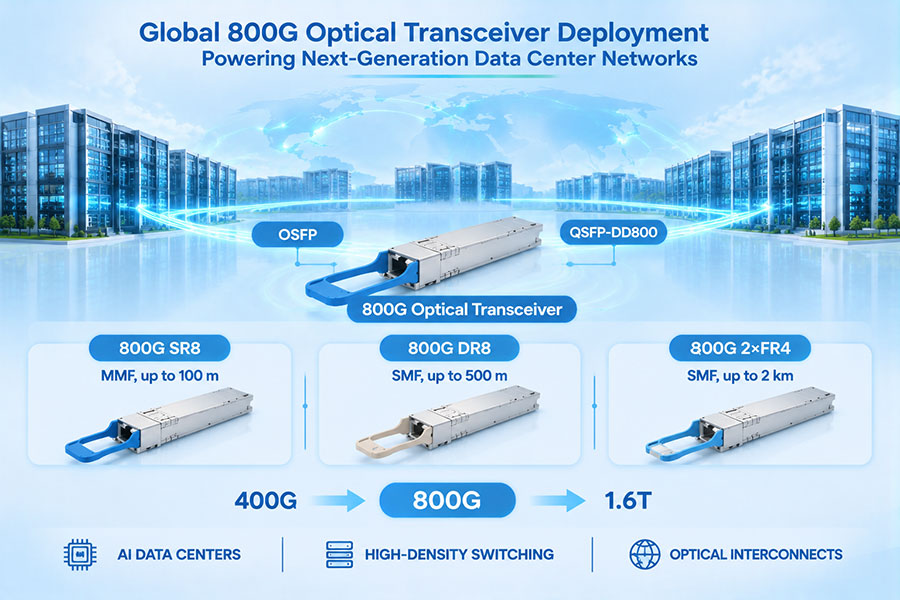
800G Optical Transceivers: SR8, 2FR4, and other high-speed optical solutions for next-generation switching platforms.
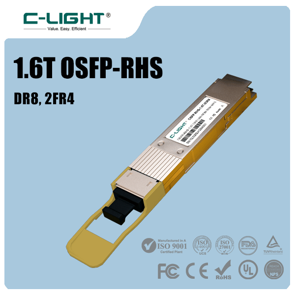
1.6T Optical Connectivity: 1.6T OSFP solutions designed for emerging high-bandwidth AI and data center applications.
DAC and AEC Cables: High-speed direct-attach and active electrical connectivity for short-reach switch-to-switch and server-to-switch links.
Optical Transport Solutions: DCO and other optical connectivity products for high-capacity network applications.
Choosing the right solution requires more than matching the nominal Ethernet speed. Host electrical specifications, PHY compatibility, optical lane architecture, FEC requirements, transmission distance, and thermal limits must all be evaluated together.
For product specifications, compatibility evaluation, and customized optical connectivity requirements, visit Contact C-LIGHT.
10. Conclusion
Ethernet MAC rate and optical line rate represent two different but closely connected aspects of high-speed networking. MAC rate defines the nominal Ethernet data capacity, while optical line rate reflects the physical transmission requirements after accounting for encoding, FEC, modulation, and other PHY functions.
As 400G, 800G, and 1.6T Ethernet technologies continue to evolve, engineers must evaluate the complete transmission architecture rather than relying solely on nominal bandwidth labels. Understanding the relationship between MAC rate, electrical lane rate, symbol rate, and optical line rate provides a more accurate foundation for transceiver selection, interoperability planning, and high-speed network deployment.
 >

 >
 >
 >
 >
 >
 >
 >