TEL:+86 132 6656 7067


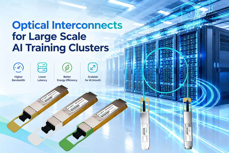
AI training clusters rely on high-bandwidth communication between GPU servers, switches, and storage systems. As models grow and more accelerators operate in parallel, the network must move large volumes of data with low latency and consistent throughput.
Optical connectivity supports this growth by providing high-speed links between servers and switches, across network tiers, and between separate data center locations. With 400G and 800G optical interfaces increasingly used in AI infrastructure, fiber selection, transceiver compatibility, and network topology have become important parts of cluster design.
1. Where Optical Connectivity Fits in AI Clusters
AI infrastructure uses different interconnects for different communication tasks. Within a server or tightly integrated computing system, GPUs may communicate through dedicated accelerator interconnects. Across servers, network interface cards and high-speed switches connect the distributed computing resources.
Optical links are particularly valuable when high bandwidth must be delivered across rack-level or longer network connections. Short connections may instead use direct-attach copper (DAC) or active optical cables (AOC), depending on distance, port compatibility, power, and cost.
Server-to-switch: Connects GPU servers to leaf switches through compatible NICs and optical interfaces.
Switch-to-switch: Connects leaf, spine, and aggregation layers to provide sufficient capacity for distributed training traffic.
Storage connectivity: Connects storage systems and data infrastructure to the network serving AI workloads.
Cluster interconnection: Links separate network domains or facilities when the architecture requires longer optical reach.
Optical cabling does not replace every electrical interconnect in an AI system. The appropriate medium depends on the distance, traffic pattern, bandwidth target, and physical design of each connection.
2. 400G and 800G Optical Links
High-speed optical interfaces help increase network capacity without requiring every connection to use multiple lower-rate ports. The choice between 400G and 800G depends on the switch architecture, endpoint interfaces, number of links, and expected traffic demand.
| Optical Rate | Typical Role | Key Design Considerations |
|---|---|---|
| 100G | Existing infrastructure and selected server or network connections | Host compatibility, reach, and available bandwidth |
| 400G | High-speed server connectivity and switch uplinks | Lane configuration, optical interface, FEC, and link distance |
| 800G | High-capacity AI fabrics and next-generation switch interconnections | Port density, module power, cooling, and fiber architecture |
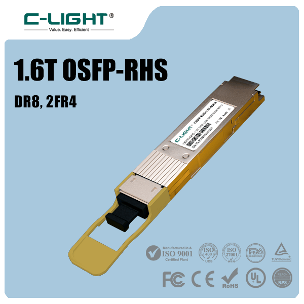
| 1.6T-class interfaces | Emerging and next-generation network designs | Supported host platforms, electrical lanes, thermal limits, and availability |
Both InfiniBand and Ethernet-based networks can support high-performance AI workloads. The selected networking architecture determines supported interfaces, congestion-management features, and compatibility requirements. An optical transceiver must match the intended system rather than being selected by data rate alone.
3. Choosing the Right Optical Transceiver
Transceiver selection affects bandwidth, reach, power consumption, cooling, and maintenance. A suitable module must match the switch or NIC port and support the required Ethernet or InfiniBand application.
| Factor | What to Check |
|---|---|
| Form factor | Confirm QSFP-DD, OSFP, or another supported interface. |
| Optical standard | Match the module to the required 400G or 800G application. |
| Fiber type | Choose multimode or single-mode fiber according to the optical interface and distance. |
| Connector | Verify LC, MPO/MTP, or other supported connector configurations and fiber polarity. |
| Power and cooling | Check module power consumption, airflow, temperature limits, and host requirements. |
| Compatibility | Validate the transceiver against the exact switch, NIC, firmware, and network configuration. |
QSFP-DD and OSFP are both used in high-speed networking. QSFP-DD offers a compact form factor with backward mechanical compatibility for supported QSFP-family modules. OSFP uses a larger mechanical design with thermal options suited to high-power applications. The host platform ultimately determines which modules can be installed and supported.
4. Fiber Type and Transmission Distance
Multimode and single-mode fiber support different optical applications. Multimode fiber is commonly used for shorter links, while single-mode fiber supports a wider range of reaches, including longer connections between network facilities.
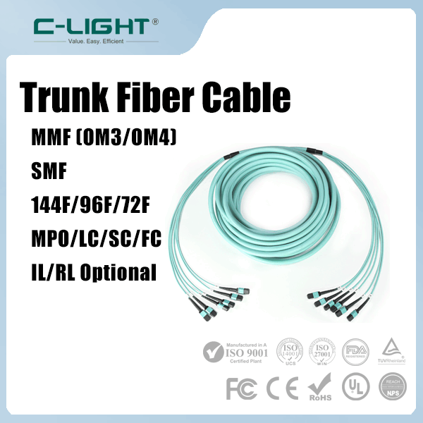
Multimode fiber: OM3 and OM4 can support suitable short-reach optical links. The maximum distance depends on the specific Ethernet or InfiniBand interface.
Single-mode fiber: OS2 is commonly used for higher-reach links. Compatible DR, FR, LR, and other optical interfaces support different distance classes.
DAC and AOC: Direct-attach copper and active optical cables are alternatives for supported short-distance connections where they meet the system requirements.
For example, some 800G DR4 single-mode transceivers support links up to 500 meters, while other optical interfaces are designed for shorter or longer distances. Such reach values apply to the particular transceiver standard and link conditions, not to every 800G module.
Before deployment, calculate the optical loss budget and check connector losses, fiber attenuation, patch panels, splices, and the specified receive-power range. Connector inspection, cleaning, and polarity verification are important for reliable high-speed links.
5. Network Topology, Congestion, and Reliability
Even with high-speed optical links, an AI cluster can underperform if the network topology creates bottlenecks. Distributed training generates synchronized traffic between servers, so link oversubscription, uneven load distribution, or insufficient switch capacity can increase communication time.
A well-designed fabric should provide sufficient bandwidth for the expected traffic patterns and maintain appropriate latency, congestion management, and resilience. Network monitoring should include port utilization, errors, packet drops, congestion indicators, and optical diagnostics where available.
Reliability also depends on consistent module qualification and maintenance. The optical interface, host firmware, FEC settings, and link configuration must work together. Keeping records of compatible modules and baseline optical power measurements can simplify troubleshooting as the cluster expands.
6. Planning Optical Connectivity for AI Training
A scalable optical design starts with the computing architecture and the communication requirements of the workload. Network planners should consider the number of GPU servers, NIC bandwidth, switch port capacity, topology, distance, and expected growth before choosing transceivers and fiber.
Calculate aggregate bandwidth requirements across server-facing and switch-to-switch links.
Choose optical interfaces that match the host equipment, reach, and fiber infrastructure.
Evaluate transceiver power consumption, thermal limits, airflow, and rack-level cooling.
Verify congestion management, link error rates, and end-to-end communication performance.
Allow capacity and fiber-path flexibility for future accelerator and network upgrades.
Optical connectivity is most effective when planned as part of the complete network rather than as an isolated component purchase. A balanced combination of GPU interconnects, NICs, switches, transceivers, and fiber helps maintain throughput as training clusters grow.
7. Conclusion
Optical connectivity is a key part of scalable AI training clusters, enabling high-bandwidth links between GPU servers, switches, storage systems, and network domains. 400G and 800G transceivers provide options for increasing network capacity, while multimode and single-mode fiber address different reach requirements.
Successful deployment depends on matching the optical interface to the network architecture, selecting compatible modules, managing congestion, and validating link performance. With suitable bandwidth planning and optical infrastructure, AI clusters can scale while maintaining reliable communication between distributed computing resources.
 >
>

 >
>
 >
>
 >
>
 >
>
 >
>
 >
>
 >
>