TEL:+86 132 6656 7067


Optical Transceiver Testing and Validation Guide
Optical transceiver testing and validation are essential for verifying that an optical module can meet its optical, electrical, functional, environmental, and interoperability requirements.
As data rates have increased from 100G and 400G to 800G and 1.6T, optical transceiver validation has become more demanding. PAM4 signaling, higher lane rates, tighter signal margins, advanced DSPs, FEC, higher power density, and more complex host interfaces all require more comprehensive testing.
A complete validation process should not rely on a single measurement such as optical output power or BER. A reliable transceiver must satisfy transmitter specifications, receiver performance, host electrical requirements, link-level behavior, thermal conditions, software and management functions, interoperability, and production consistency.
1. Why Optical Transceiver Testing Is Important
An optical transceiver sits at the interface between electrical equipment and optical fiber. A failure in either domain can result in packet errors, link instability, reduced transmission distance, or complete loss of connectivity.
Testing is therefore used to answer several questions:
Does the transmitter generate the required optical signal?
Can the receiver correctly recover the incoming data?
Does the module maintain performance under realistic channel conditions?
Does the module interoperate with the intended switch, NIC, or transport equipment?
Does performance remain stable across temperature and operating conditions?
Can the manufacturing process repeatedly produce compliant modules?
These questions require different test methods at different stages of the product lifecycle.
2. Optical Transceiver Testing Stages
Testing is normally divided into several stages rather than performed as one final inspection.
| Stage | Primary Objective | Typical Tests |
|---|---|---|
| Component Characterization | Evaluate individual lasers, photodiodes, drivers, DSPs, and PICs | Optical power, wavelength, bandwidth, noise, electrical characteristics |
| Module Development | Verify complete transceiver design | Eye, BER, TDECQ, sensitivity, power, temperature |
| Compliance Testing | Compare performance with applicable standards | Electrical and optical compliance measurements |
| Interoperability Testing | Verify operation with target hosts and network equipment | Link-up, BER, traffic, FEC, lane behavior |
| Production Testing | Screen every module efficiently | Power, wavelength, eye, basic functional and communication tests |
| Field Validation | Verify deployed links | BER, traffic, loss, latency, optical diagnostics |
3. Optical Transceiver Test Setup
A typical laboratory test environment combines optical and electrical test equipment.
| Equipment | Primary Function |
|---|---|
| BERT | Generates and analyzes high-speed test patterns and BER |
| Sampling Oscilloscope | Measures optical or electrical waveforms and eye diagrams |
| Optical Power Meter | Measures optical power |
| Optical Spectrum Analyzer | Measures wavelength, spectrum, channel spacing, and OSNR where applicable |
| Optical Attenuator | Controls received optical power during receiver testing |
| Optical Switch | Automates multiple optical paths |
| Temperature Chamber | Tests module performance across temperature |
| Traffic Generator/Analyzer | Tests Ethernet or other protocol traffic at system level |
| High-Speed Electrical Fixtures | Connects the module to electrical test equipment with controlled impedance |
For high-speed modules, the test fixture itself becomes part of the measurement system. Calibration, insertion loss, connector quality, and fixture repeatability can significantly influence the results.
4. Optical Output Power Test
Optical output power is one of the most fundamental transmitter measurements.
It verifies that the transmitter generates sufficient optical power for the intended link while remaining within the specified operating range.
Testing should record the power of each optical lane where the architecture contains multiple lanes.
| Measurement | Purpose |
|---|---|
| Average Optical Power | Measures average transmitted optical power |
| Per-Lane Power | Checks lane-to-lane consistency |
| Power Variation | Identifies unstable or poorly balanced transmit paths |
| Temperature Drift | Checks power stability across operating temperature |
Output power alone does not prove transmitter quality. A module can have acceptable average power while still showing poor eye quality, excessive jitter, distortion, or other signal impairments.
5. Wavelength and Optical Spectrum Testing
Wavelength testing verifies that the optical signal is operating within the required wavelength range.
This is particularly important for WDM modules where several optical channels must remain within specified wavelength windows.
Typical measurements include center wavelength, spectral width, channel spacing, side modes, and optical signal-to-noise characteristics where applicable.
| Optical Measurement | Typical Application |
|---|---|
| Center Wavelength | Fixed-wavelength and WDM transceivers |
| Wavelength Accuracy | CWDM/DWDM systems |
| Spectral Width | Laser characterization |
| OSNR | Long-reach and coherent optical systems |
| Channel Spacing | DWDM validation |
For coherent modules, optical spectrum and OSNR testing become particularly important because multiple wavelengths can coexist in the same fiber system.
6. Optical Eye Diagram Testing
An optical eye diagram provides a visual representation of the signal quality over many symbol periods.
It can reveal amplitude imbalance, timing variation, noise, distortion, level separation, and other signal impairments.
For NRZ, the eye diagram contains a single primary eye opening. PAM4 produces three vertically stacked eye openings and requires more detailed analysis.
| Eye Measurement | What It Indicates |
|---|---|
| Eye Height | Vertical signal margin |
| Eye Width | Timing margin |
| Level Separation | Quality of PAM4 signal levels |
| Crossing Behavior | Timing and amplitude symmetry |
| Jitter | Timing variation |
7. PAM4 Signal Testing
PAM4 is widely used in high-speed optical transceivers because four signal levels can represent two bits per symbol.
The advantage is higher data throughput at a given symbol-rate range. The tradeoff is smaller vertical eye openings and increased sensitivity to noise, nonlinear distortion, crosstalk, and other channel impairments.
For 400G, 800G, and emerging 1.6T modules, PAM4 measurements can include:
Eye diagrams
TDECQ
OMA
Extinction ratio
RLM
Jitter
Level separation
Amplitude measurements
Each lane should be evaluated because one weak lane can limit the complete module.
8. TDECQ Testing
TDECQ, or Transmitter and Dispersion Eye Closure Quaternary, is a key measurement for PAM4 optical transmitters.
It evaluates the effective optical power penalty of a measured PAM4 transmitter compared with an ideal reference transmitter after applying the specified reference equalization methodology.
A lower TDECQ value indicates a smaller power penalty and generally better transmitter signal quality.
TDECQ is particularly important for high-speed PAM4 optical modules because conventional average optical power measurements cannot fully describe the quality of a multi-level optical waveform.
9. OMA, Extinction Ratio, and RLM
Additional transmitter measurements help describe the amplitude characteristics of the optical signal.
| Measurement | Purpose |
|---|---|
| OMA | Describes optical modulation amplitude |
| Extinction Ratio | Compares optical high and low levels in applicable signal formats |
| RLM | Evaluates relative level modulation characteristics of a PAM4 transmitter |
| Average Power | Measures the overall average transmitted optical power |
| TDECQ | Evaluates PAM4 transmitter quality using a reference-equalized measurement |
These measurements should be interpreted together. No single transmitter parameter completely describes a high-speed optical waveform.
10. BER Testing
Bit Error Rate testing determines how accurately transmitted information is recovered by the receiver.
A BERT generates a known test pattern and compares the received data with the expected sequence.
The basic BER calculation is:
BER = Number of Incorrect Bits / Total Number of Transmitted Bits
For example, if one incorrect bit is detected after transmitting 1012 bits, the measured BER is 10-12.
The test duration required for a meaningful BER measurement depends on the target BER, confidence level, test method, and standard.
11. Pre-FEC BER and Post-FEC Performance
Modern high-speed optical systems often rely on FEC to correct transmission errors. This makes it important to distinguish raw or pre-FEC errors from the final corrected link behavior.
| Metric | Meaning |
|---|---|
| Raw BER | Bit error behavior before FEC processing |
| Pre-FEC BER | Error rate measured before FEC correction |
| FEC Error Statistics | Error distribution entering the correction mechanism |
| Post-FEC BER | Residual errors after FEC processing where measurable |
| BLER | Block or codeword error behavior used by some high-speed test methods |
| FLR | Frame loss under specified stressed conditions |
Testing only post-FEC behavior can hide a deteriorating optical link. Pre-FEC error statistics and FEC margin provide additional information about how close the link is to its performance limit.
12. FEC Validation
FEC validation is especially important for high-speed PAM4 systems.
A complete FEC test should evaluate both normal operation and stressed conditions. The test may intentionally introduce controlled noise, jitter, or other impairments to determine how the module and host behave near the expected operating boundary.
Important measurements can include:
Pre-FEC BER
Corrected error count
Uncorrectable error count
Error distribution
Codeword behavior
BLER
Frame Loss Ratio
FEC margin
For large-scale AI and data center networks, FEC validation is particularly important because thousands of links can operate simultaneously and small per-link error differences can affect overall system behavior.
13. Receiver Sensitivity Testing
Receiver sensitivity is the minimum input optical power at which the receiver can maintain the required performance under the specified test conditions.
A typical receiver sensitivity test uses a variable optical attenuator to gradually reduce the input optical power.
The test procedure generally includes:
Establishing a stable reference test pattern
Connecting the transmitter or optical source to the receiver
Adjusting the optical power through an attenuator
Recording BER or another specified error metric
Determining the power level corresponding to the required performance
The resulting sensitivity should be compared with the applicable module specification rather than evaluated using a universal value.
14. Receiver Overload and Dynamic Range
Receiver testing should not stop at sensitivity. The receiver also needs to operate correctly when the incoming optical power is relatively high.
Receiver overload testing determines the maximum input power that can be tolerated while maintaining the required performance.
| Receiver Measurement | Purpose |
|---|---|
| Sensitivity | Determines minimum required input power |
| Overload | Determines maximum acceptable input power |
| Dynamic Range | Describes the useful input power range |
| LOS Threshold | Tests loss-of-signal behavior where applicable |
15. Optical Power Budget Validation
The optical power budget determines whether a complete link has sufficient margin for transmission.
The fundamental relationship is:
Maximum Allowable Loss = Transmitter Output Power − Receiver Sensitivity
Total link loss can include:
Fiber attenuation
Connector loss
Patch-panel loss
Splice loss
Splitter or passive device loss
Other system losses
Validation should verify that the measured link loss remains within the available optical budget after applying the required system margin.
16. Electrical Interface Testing
An optical transceiver also contains a high-speed electrical interface between the host system and the optical engine.
This interface must be tested independently from the optical path.
| Electrical Measurement | Purpose |
|---|---|
| Eye Diagram | Evaluate electrical waveform quality |
| Jitter | Measure timing variation |
| Rise/Fall Time | Characterize signal transitions where applicable |
| Voltage Levels | Verify electrical amplitude requirements |
| Insertion Loss | Evaluate channel loss |
| Return Loss | Evaluate reflections |
| Crosstalk | Measure coupling between electrical lanes |
At 800G and 1.6T, host electrical testing becomes increasingly important because module performance depends strongly on the quality of the electrical channel between the switch ASIC, connector, PCB, and transceiver.
17. Temperature and Environmental Testing
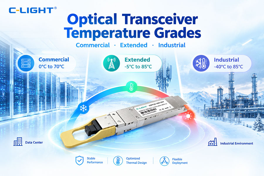
Optical transceivers can experience changes in optical power, wavelength, receiver sensitivity, laser characteristics, and electrical performance as temperature changes.
Environmental validation should therefore evaluate the complete module across the specified operating range.
| Test Condition | Typical Objective |
|---|---|
| Low Temperature | Verify startup and stable optical/electrical operation |
| Room Temperature | Establish baseline performance |
| High Temperature | Verify thermal performance and signal stability |
| Temperature Cycling | Evaluate performance stability during repeated temperature changes |
| Humidity | Evaluate environmental resistance where applicable |
| Mechanical Stress | Evaluate robustness where required |
Industrial and telecom modules may require broader environmental qualification than standard data center modules.
18. Interoperability and Host Validation
A module that passes standalone optical tests may still fail when installed in an actual network platform.
Interoperability testing therefore verifies the complete path between the optical transceiver and its host equipment.
Typical tests include:
Module recognition
CMIS management communication where applicable
Link establishment
Lane mapping
Speed configuration
FEC behavior
Traffic throughput
BER under load
Temperature stability
Hot-plug and restart behavior
Testing with multiple switch, NIC, router, or transport platforms can identify host-specific interoperability issues that cannot be found through optical characterization alone.
19. Production Testing and Quality Control
Production testing must balance measurement coverage, accuracy, test time, and manufacturing cost.
Not every development measurement needs to be repeated with the same depth on every production unit.
| Production Test | Typical Purpose |
|---|---|
| Module Identification | Verify EEPROM or management information |
| Optical Power | Screen transmitter output |
| Wavelength | Verify optical center wavelength |
| Basic Eye/TDECQ | Screen transmitter quality for high-speed PAM4 modules |
| BER or Functional Test | Verify communication path |
| Power Consumption | Verify module power behavior |
| Temperature Screening | Identify thermal or marginal units where required |
| Host Compatibility | Verify target platform behavior |
Automated test software should record per-lane results and traceability data so that manufacturing trends can be identified before they become field reliability problems.
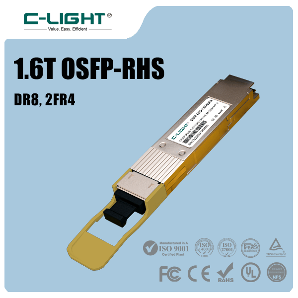
20. 400G, 800G, and 1.6T Validation
Higher-speed optical modules require increasingly capable test methodologies.
| Generation | Key Validation Focus |
|---|---|
| 100G | Optical power, sensitivity, BER, wavelength, electrical compliance |
| 400G | PAM4 eye, TDECQ, BER, FEC, lane performance, electrical signal quality |
| 800G | Multi-lane PAM4, TDECQ, FEC-aware receiver testing, interoperability, power and thermal behavior |
| 1.6T | Higher lane-rate electrical/optical validation, PAM4 signal quality, FEC, host interface, thermal and system interoperability |
At 1.6T, validation may involve multiple 200G-class lanes and emerging higher-lane-rate architectures. The test equipment must have sufficient bandwidth, channel count, calibration accuracy, and automation to measure all relevant lanes reliably.
21. Testing 1.6T Optical Transceivers
1.6T optical transceivers place additional pressure on both the optical and electrical test environment.
The validation process may need to include optical TDECQ, OMA, extinction ratio, RLM, BER, FEC behavior, host electrical performance, power consumption, and temperature stability.
For electrical interfaces, fixture and connector quality become especially important because small channel impairments can affect measurement accuracy at high lane rates.
Current industry testing activity for IEEE P802.3dj 1.6TbE includes stressed receiver sensitivity and transmitter functional testing, together with FEC-related performance evaluation. This reflects the growing need for FEC-aware validation rather than relying only on conventional optical power and BER measurements.
22. Coherent Optical Transceiver Testing
Coherent optical transceivers require additional measurements beyond conventional short-reach direct-detection modules.
| Test Parameter | Coherent Application |
|---|---|
| Optical Power | Verify transmitter and receiver operating levels |
| Wavelength | Verify WDM channel position |
| OSNR | Evaluate optical signal quality |
| Chromatic Dispersion | Characterize transmission impairment |
| Polarization Parameters | Evaluate polarization behavior |
| BER | Verify data recovery performance |
| Pre/Post-FEC Performance | Evaluate coherent DSP and FEC margin |
| Loopback | Support module self-diagnostics and data-path testing |
For coherent DCI and metro modules, validation should cover the transceiver itself and the optical line environment in which the module is expected to operate.
23. Test Automation and Data Analysis
Manual testing becomes inefficient when a module contains multiple optical and electrical lanes.
Automated test systems can control instruments, configure test patterns, capture measurements, calculate margins, and generate production or engineering reports.
Automation should ideally support:
Multi-lane testing
Automatic calibration checks
Test-pattern configuration
Instrument control
Pass/fail evaluation
Data logging
Per-lane analysis
Statistical process monitoring
Automatic report generation
For high-volume manufacturing, reducing test time without reducing measurement reliability is a major objective.
24. Optical Transceiver Testing Best Practices
A robust validation process should combine standards compliance with application-level testing.
The following approach provides a practical framework:
| Step | Validation Objective |
|---|---|
| 1. Define Requirements | Identify applicable standard, data rate, reach, fiber, wavelength, host and environmental requirements |
| 2. Calibrate Equipment | Verify measurement accuracy and fixture condition |
| 3. Test Transmitter | Measure power, waveform, wavelength and signal quality |
| 4. Test Receiver | Measure sensitivity, overload and error performance |
| 5. Test FEC | Evaluate error correction and margin |
| 6. Test Electrical Interface | Verify host-side signal integrity |
| 7. Test Temperature | Verify stable operation over the defined range |
| 8. Test Interoperability | Verify actual host and network behavior |
| 9. Analyze Margin | Determine how far performance is from specification limits |
| 10. Record Traceability | Maintain complete test and production records |
The goal should be to determine not only whether a module passes, but also how much performance margin remains under realistic operating conditions.
25. Conclusion: Optical Transceiver Testing and Validation
Optical transceiver testing is a multi-layer process that combines optical measurements, electrical validation, protocol testing, environmental qualification, and interoperability verification.
For traditional modules, core measurements include optical output power, wavelength, receiver sensitivity, BER, and electrical interface performance.
For high-speed 400G and 800G PAM4 modules, testing must expand to include eye diagrams, TDECQ, OMA, RLM, jitter, pre-FEC BER, FEC behavior, and multi-lane analysis.
For emerging 1.6T modules, even higher electrical and optical lane rates increase the importance of fixture quality, calibration, high-bandwidth instrumentation, FEC-aware receiver testing, thermal analysis, and host interoperability.
A complete validation strategy should therefore move from component characterization → module compliance → link validation → interoperability → environmental testing → production quality control.
For optical transceiver manufacturers, rigorous testing is essential not only for demonstrating compliance but also for achieving consistent field performance and reliable operation at scale.
 >
>

 >
>
 >
>
 >
>
 >
>
 >
>
 >
>
 >
>