TEL:+86 132 6656 7067


Choosing the right optical transceiver is essential for building a reliable, cost-effective, and scalable fiber optic network. Different transceivers support different data rates, transmission distances, wavelengths, fiber types, connector interfaces, and network protocols. Selecting a module based on only its transmission speed or package size can result in incompatibility, insufficient optical power budget, or unnecessary deployment costs.
From 1G and 10G Ethernet to 100G, 400G, 800G, and 1.6T optical interconnects, the correct selection process starts with the network requirements and ends with compatibility verification and link testing. Data centers, enterprise networks, telecommunications infrastructure, industrial systems, and AI computing clusters may all require different optical solutions.
A reliable selection process should evaluate the complete link, including both transceivers, the optical fiber, connectors, intermediate components, and the host devices. The following factors provide a practical framework for selecting optical transceivers for new deployments, upgrades, and replacement projects.
1. Identify the Application and Network Requirements
Before selecting an optical transceiver, define the application and network environment. A short server-to-switch connection in a data center has different requirements from a 10 km enterprise link or a long-distance telecommunications connection.
Start by identifying the equipment being connected, the required data rate, the physical distance between endpoints, the installed fiber infrastructure, and the expected network architecture.
Typical applications include:
Enterprise Ethernet networks and campus connectivity
Data center switch-to-server and switch-to-switch connections
AI data centers and high-performance computing clusters
Telecommunications and 5G transport networks
FTTH, FTTO, and PON access networks
Industrial automation and specialized communication systems
Application requirements determine which optical technologies are suitable. For example, a short-reach data center connection may use a VCSEL-based multimode transceiver, while a 10 km single-mode link typically requires a different wavelength and optical architecture.
2. Match the Data Rate and Network Protocol
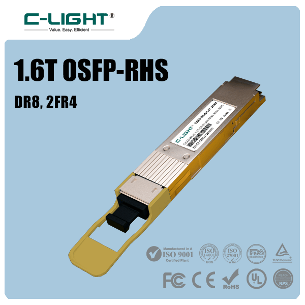
The first technical requirement is the data rate supported by the host equipment and the optical link. Common Ethernet transceiver speeds include 1G, 10G, 25G, 40G, 50G, 100G, 200G, 400G, and 800G, with 1.6T-class solutions emerging for next-generation high-bandwidth systems.
However, the data rate alone does not establish compatibility. The host port, network protocol, electrical interface, modulation format, and supported optical standard must also match the intended application.
| Network Speed | Common Form Factor | Typical Application |
|---|---|---|
| 1G | SFP | Access switches, enterprise networks, industrial connectivity |
| 10G | SFP+ | Server connections, enterprise uplinks, aggregation networks |
| 25G | SFP28 | Data center servers, switch connections, 5G fronthaul |
| 40G | QSFP+ | Legacy data center uplinks and network aggregation |
| 100G | QSFP28 | Data center switching, backbone links, high-performance networks |
| 200G | QSFP56 and other supported formats | High-density data center and computing networks |
| 400G | QSFP-DD, OSFP, QSFP112 | Cloud data centers, AI fabrics, high-speed switching |
| 800G | OSFP, QSFP-DD and platform-supported formats | AI clusters, HPC, hyperscale data centers |
| 1.6T | Platform-specific next-generation formats | Emerging high-bandwidth AI and data center interconnects |
These are common examples rather than a universal compatibility table. Available speeds, module formats, and protocol support depend on the specific equipment generation. A module with the correct nominal speed may still fail to operate if the host port does not support its electrical interface or operating mode.
3. Select the Correct Optical Transceiver Form Factor
The form factor defines the physical package and electrical interface of the transceiver. It affects port density, supported data rates, thermal design, installation space, and compatibility with the host device.
Common form factors include SFP, SFP+, SFP28, QSFP+, QSFP28, QSFP56, QSFP-DD, OSFP, and QSFP112. Each format serves particular generations of network equipment and may support different optical or direct-attach cable options.
When choosing a form factor, confirm the following:
The host device has a compatible physical port.
The port supports the required data rate and electrical interface.
The module's power consumption is within the host's supported limit.
The available cooling and airflow are appropriate for the module.
The module's physical dimensions and installation requirements match the platform.
Do not assume that modules with similar physical sizes are interchangeable. SFP+, SFP28, and other related formats may have overlapping capabilities on some platforms, but operational support must be verified against the specific switch, router, server, or NIC.
4. Determine the Required Transmission Distance
Transmission distance is one of the most important factors when selecting an optical transceiver. A module designed for a short-reach connection may not provide sufficient optical performance for a longer link, while an unnecessarily long-reach module can increase cost and may require additional attention to received optical power.
Measure the complete optical path between the two endpoints, including any patch panels, intermediate connections, fiber distribution frames, and other passive components. Select a module whose supported reach and optical budget accommodate the actual link conditions.
Typical reach categories include:
| Reach Category | Typical Application | Important Consideration |
|---|---|---|
| Short reach | Connections within racks and data center rooms | Often uses multimode fiber or short-reach single-mode designs |
| Approximately 500 m | Building and data center connections | Single-mode options such as DR designs may be suitable |
| Approximately 2 km | Campus, data center, and aggregation links | FR and related single-mode architectures may apply |
| Approximately 10 km | Enterprise, metro access, and telecom links | LR and other long-reach single-mode designs are common |
| 40 km or longer | Extended-reach telecom and transport networks | Requires careful optical budget and system compatibility checks |
These reach categories are illustrative. The actual distance supported by a transceiver depends on its optical specification, fiber characteristics, connector loss, link architecture, and applicable standard. Always verify the exact product datasheet instead of relying only on a category name.
5. Choose Between Multimode Fiber and Single-Mode Fiber
The fiber type must match the selected transceiver. Multimode fiber (MMF) and single-mode fiber (SMF) have different core structures, optical propagation characteristics, typical wavelengths, and supported transmission distances.
Multimode fiber is widely used for short-reach links in data centers. It is commonly paired with 850 nm VCSEL-based transceivers, such as SR modules. OM3 and OM4 are common multimode fiber grades, with supported reach depending on the transceiver generation and data rate.
Single-mode fiber is widely used for longer-distance connectivity and high-speed single-mode optical architectures. Common modules operate around 1310 nm or 1550 nm, with DR, FR, LR, ER, and other designs supporting different reach and optical requirements.
| Characteristic | Multimode Fiber (MMF) | Single-Mode Fiber (SMF) |
|---|---|---|
| Common Wavelength | 850 nm | 1310 nm and 1550 nm, among others |
| Typical Laser Technology | VCSEL | DFB, EML, silicon photonics-based sources, and other implementations |
| Typical Application | Short-reach data center links | Data center, enterprise, metro, and telecom links |
| Fiber Types | OM3, OM4, OM5 | OS1, OS2 |
| Distance Consideration | Usually optimized for shorter links | Suitable for a broad range of single-mode reaches |
Using a module designed for one fiber type on an incompatible fiber infrastructure can prevent the link from operating correctly or reduce performance. Verify fiber type, wavelength, connector arrangement, and reach as one complete set of requirements.
6. Match the Wavelength and Optical Architecture
Wavelength determines the optical region used for transmission and must be consistent with the intended fiber link and transceiver design. Common optical communication wavelengths include 850 nm, 1310 nm, and 1550 nm, as well as wavelength-specific implementations used in CWDM and DWDM systems.
For a typical short-reach multimode connection, an 850 nm VCSEL-based SR module is a common choice. For single-mode links, 1310 nm-class transceivers are widely used. Some long-distance and wavelength-division-multiplexed systems use 1550 nm-class optics or more specialized optical technologies.
Bidirectional (BiDi) transceivers require special attention. A BiDi pair transmits and receives at different wavelengths over one fiber strand. The modules at the two ends must have complementary transmit and receive wavelengths.
For CWDM and DWDM links, confirm the assigned wavelength or channel, the optical line-system requirements, and whether the transceiver is designed for the required multiplexing architecture.
7. Check the Optical Connector and Fiber Arrangement
The connector interface must match the existing fiber infrastructure and the optical port on the module. Common interfaces include duplex LC, simplex LC, MPO/MTP, and other compact or high-density connector systems.
Duplex LC is widely used for two-fiber single-mode and multimode links. BiDi modules commonly use a single-fiber connection. Parallel optical modules, including many SR8 and DR4 implementations, may use MPO/MTP interfaces.
Before ordering a transceiver, verify:
Connector family and physical interface
Simplex, duplex, or parallel-fiber arrangement
Fiber count and polarity requirements
UPC or APC polish where applicable
Compatibility with patch panels, cassettes, and existing cabling
Connector appearance alone does not guarantee optical compatibility. For example, APC and UPC connectors should not be mated together. Parallel-fiber links also require the correct lane mapping and polarity across the complete path.
8. Understand SR, DR, FR, LR, and ER Categories
Optical reach labels provide a useful starting point for module selection, but the precise meaning and supported reach depend on the data rate and applicable standard. The same category name should not be assumed to guarantee identical performance across every generation or vendor implementation.
| Category | General Meaning | Common Fiber or Application |
|---|---|---|
| SR | Short Reach | Commonly multimode fiber for short-distance links |
| DR | Data Center Reach | Typically single-mode parallel optics or related single-mode implementations |
| FR | Two-kilometer-class reach in many Ethernet generations | Typically single-mode fiber |
| LR | Long Reach | Commonly 10 km-class single-mode applications |
| ER | Extended Reach | Often used for longer-distance single-mode links, such as 40 km-class implementations |
For example, a 400G DR4 module and a 400G FR4 module can differ in their optical lane arrangement, connector type, wavelength architecture, and supported reach. The module name should therefore be checked against its full optical specification and not used as the sole selection criterion.
9. Calculate the Optical Link Budget
The optical link budget helps determine whether the transmitter provides sufficient optical power for the receiver after accounting for losses along the path. It is particularly important for links with multiple patch panels, connectors, splices, or long fiber runs.
A simplified calculation is:
Available Optical Budget = Minimum Transmitter Output Power − Receiver Sensitivity
The estimated path loss should include fiber attenuation, connector loss, splice loss, and other relevant optical penalties. A practical design also allows margin for aging, environmental changes, maintenance, and measurement uncertainty.
For example, if the minimum transmitter output power is -3 dBm and receiver sensitivity is -10 dBm, the simplified available budget is 7 dB. The actual link must remain within the manufacturer's specified operating limits.
Do not check only whether the received signal is strong enough. Excessively high received optical power can also exceed the receiver's maximum input specification. For some longer-reach optics used over short links, an appropriate optical attenuator may be needed.
10. Check Optical Lane Count and Breakout Requirements
High-speed transceivers often use multiple optical lanes to reach their aggregate data rate. The lane count, electrical interface, optical interface, modulation format, and breakout capability determine how the module connects to switches, servers, or other transceivers.
For example, some 400G modules support a 4 × 100G breakout configuration, while some 800G modules can support particular 2 × 400G or other breakout arrangements. These options depend on the exact transceiver design, host platform, firmware, cabling, and port configuration.
Before deployment, confirm:
The number of electrical and optical lanes
The data rate supported by each lane
The host port's breakout capabilities
The required MPO/MTP or LC connection arrangement
The cable polarity and lane mapping
Compatibility with the receiving modules at the remote endpoints
Do not assume that any module with the correct aggregate data rate can operate in every breakout mode. Verify the supported configuration before purchasing the modules and cabling.
11. Verify Host-Device Compatibility
Transceiver compatibility involves more than physical fit. The host switch, router, server, or network interface card must support the module's form factor, data rate, electrical interface, optical standard, power requirements, and operating mode.
Some platforms also impose vendor-specific restrictions or require specific firmware versions. Third-party modules may be accepted on some systems but restricted or unsupported on others.
For reliable deployment, check the host device's compatibility list, the module's supported platform information, the required software version, and the transceiver's coding or identification requirements.
It is also important to distinguish device compatibility from optical interoperability. Two modules may each work in their own host devices but still fail to establish a link if their optical standards, wavelengths, lane configurations, or transmission modes do not match.
12. Evaluate Power Consumption and Thermal Performance
Power consumption becomes increasingly important as optical module speeds rise. High-density switches may operate many transceivers simultaneously, so the combined power demand can influence system capacity, cooling requirements, and deployment cost.
Check the module's typical and maximum power consumption, the host port's power allowance, and the cooling capability of the equipment. For high-speed modules, airflow direction and the surrounding port population may also affect supported operating conditions.
Do not assume that all modules in the same form factor consume the same amount of power. Two transceivers with identical nominal data rates can have different power requirements because of differences in reach, optical architecture, DSP, laser technology, and implementation.
13. Consider Operating Temperature and Deployment Environment
Optical transceivers are available with different operating temperature ranges. Commercial, extended-temperature, and industrial-temperature variants are intended for different environmental conditions.
Commercial modules commonly specify an operating range around 0°C to 70°C, while certain extended or industrial versions support broader ranges. Exact temperature limits vary by product and must be confirmed in the datasheet.
For installation in outdoor cabinets, industrial facilities, transportation systems, or equipment with limited cooling, evaluate both ambient temperature and the actual thermal environment near the module. Electrical noise, vibration, dust, and equipment maintenance conditions may also influence the suitability of the overall installation.
14. Check Digital Diagnostics and Monitoring
Digital Optical Monitoring (DOM), also referred to as Digital Diagnostics Monitoring (DDM), can provide useful information about transceiver operating conditions. Supported measurements commonly include temperature, supply voltage, laser bias current, transmit optical power, and receive optical power.
These diagnostic values help engineers verify the optical link, identify abnormal conditions, and troubleshoot problems during deployment and maintenance.
Before selecting a module for a network that relies on remote monitoring, confirm that the transceiver supports the required diagnostic features and that the host device and software can read and report the relevant information.
Diagnostic support and reporting capabilities can vary by module and platform. Their presence should be verified rather than assumed from the form factor alone.
15. Confirm Standards and Interoperability
Industry standards help define the physical-layer behavior and optical requirements of Ethernet transceivers. Selecting modules with the correct standard is important for interoperability between network devices and for ensuring that the intended link can operate at the required speed and distance.
However, the same nominal data rate does not guarantee interoperability. For example, two 100G transceivers may use different fiber types, optical wavelengths, modulation approaches, connector arrangements, or physical-layer specifications.
Before ordering, verify the supported Ethernet or other network protocol, the relevant optical standard, the modulation format, the number of lanes, and the required link configuration. For non-Ethernet applications such as InfiniBand, Fibre Channel, or PON, confirm that the module is specifically designed for the intended protocol and host environment.
16. Check FEC and Host Configuration Requirements
Forward Error Correction (FEC) is an important consideration in many high-speed optical links. It helps correct transmission errors, but its implementation and requirements depend on the protocol, physical-layer specification, transceiver architecture, and host equipment.
Before deployment, determine whether the selected link requires a particular FEC mode and confirm that both endpoints and the host configuration support the required operation.
Do not assume that FEC can always be disabled or that two modules with the same aggregate data rate support identical FEC settings. Unsupported configurations may prevent the link from coming up or may result in poor error performance.
17. Compare Optical Transceivers with DAC, AOC, and AEC
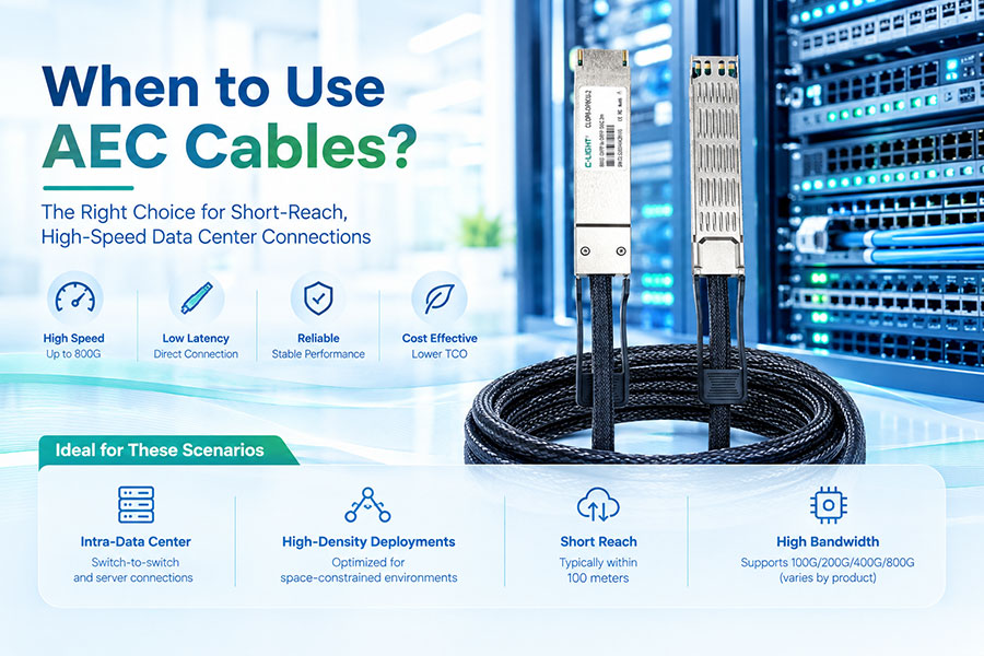
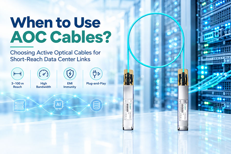
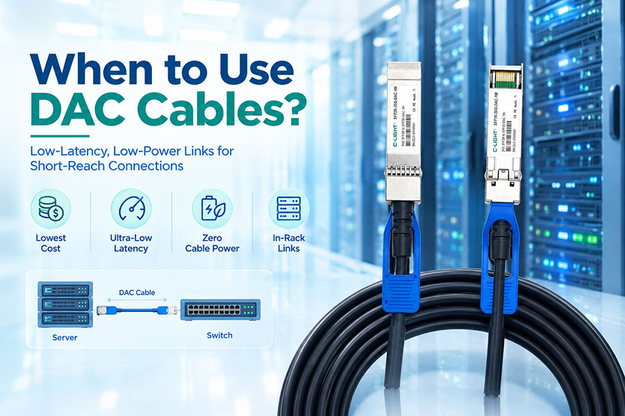
An optical transceiver is not always the most suitable interconnect for every network link. Direct Attach Copper (DAC), Active Optical Cable (AOC), and Active Electrical Cable (AEC) solutions can be alternatives for certain short-reach connections.
| Interconnect Type | Transmission Medium | Typical Advantage | Key Consideration |
|---|---|---|---|
| Optical Transceiver + Fiber | Optical fiber | Flexible reach and reusable cabling infrastructure | Requires compatible transceivers and fiber connections |
| DAC | Copper twinax cable | Simple and cost-effective for suitable short links | Cable length, weight, and routing constraints |
| AOC | Optical fiber integrated into a cable assembly | Lightweight cable assembly for supported short- and medium-reach links | Fixed cable assembly and endpoint compatibility |
| AEC | Active electrical cable | Extends electrical connectivity over supported cable lengths | Host support, power consumption, and cable specifications |
DAC is often suitable for short connections within or between adjacent racks. AOC provides an integrated optical cable solution, while AEC uses active electronics to support its electrical link. Pluggable optical transceivers and separate fiber cabling may offer greater flexibility for structured cabling and longer-distance deployment.
The best option depends on link distance, data rate, cable routing, power requirements, port compatibility, maintenance needs, and total cost.
18. Balance Cost, Reliability, and Future Scalability
The lowest purchase price does not necessarily produce the lowest total deployment cost. Module price should be evaluated alongside compatibility, optical performance, power consumption, required cabling, maintenance effort, and operational reliability.
For networks expected to grow, consider whether the selected transceiver architecture supports planned capacity increases, future port upgrades, and the existing fiber infrastructure. Single-mode cabling may provide useful flexibility for a broad range of future link distances, while multimode solutions can remain cost-effective for suitable short-reach applications.
Reliability also depends on product quality and verification. Evaluate the supplier's product documentation, quality-control procedures, compatibility testing, warranty terms, and technical support capability. These factors help reduce deployment risk and simplify future network expansion.
19. Avoid Common Optical Transceiver Selection Mistakes
Several common mistakes can lead to link failures, unexpected costs, or performance problems.
Choosing only by data rate: The correct speed does not guarantee that the wavelength, fiber, protocol, or host interface will match.
Ignoring the actual fiber type: Multimode and single-mode modules are designed for different optical link configurations.
Using nominal distance alone: Connector loss, splices, patch panels, optical budget, and receiver limits must also be considered.
Overlooking compatibility: The module must be supported by the specific host device and operating software.
Ignoring power and cooling: High-power modules can exceed platform limits or require specific airflow conditions.
Assuming all connectors are interchangeable: Connector polish, fiber polarity, lane mapping, and connector family must be correct.
Neglecting endpoint matching: Both ends of the link must support compatible optical specifications and operating modes.
Skipping link testing: A successful physical installation does not by itself confirm adequate optical power or error performance.
Checking these requirements before purchasing the modules can reduce installation problems and help ensure stable network operation.
20. A Practical Optical Transceiver Selection Process
A structured selection process helps simplify product comparison and ensures that important technical requirements are not overlooked.
Use the following checklist when preparing a transceiver specification:
| Selection Item | Information to Confirm |
|---|---|
| Application | Data center, enterprise, telecom, industrial, access, or AI network |
| Data Rate and Protocol | Required speed, Ethernet or other protocol, and physical-layer specification |
| Host Equipment | Switch, router, server, NIC, port type, and software version |
| Form Factor | SFP, SFP+, SFP28, QSFP28, QSFP-DD, OSFP, or another supported format |
| Transmission Distance | Measured link length plus allowance for the complete optical path |
| Fiber Type | OM3, OM4, OM5, OS1, OS2, or the specific installed fiber |
| Wavelength and Optics | SR, DR, FR, LR, BiDi, CWDM, DWDM, or other appropriate architecture |
| Connector and Fiber Count | LC, MPO/MTP, simplex, duplex, parallel fibers, and polarity |
| Optical Budget | Transmitter output, receiver sensitivity, path loss, and required margin |
| Power and Temperature | Host power allowance, airflow, ambient temperature, and operating limits |
| Monitoring and FEC | Required diagnostics, FEC mode, and host configuration |
| Validation | Host compatibility, remote-end interoperability, optical measurements, and link testing |
C-LIGHT provides optical connectivity solutions across multiple data rates and application categories, including SFP/SFP28, 100G, 400G, 800G, and next-generation high-speed interconnects. When requesting a recommendation or customized solution, providing the host model, required speed, link distance, fiber type, connector, and operating environment makes it easier to identify a suitable product and verify compatibility.
21.Conclusion
Choosing an optical transceiver requires more than matching a data rate or selecting a familiar form factor. The correct module must meet the requirements of the complete optical link, including the host interface, transmission distance, fiber type, wavelength, connector configuration, optical power budget, power consumption, and operating environment.
For short-reach data center connections, VCSEL-based multimode transceivers or DAC/AOC solutions may be appropriate. Single-mode transceivers provide broader options for kilometer-scale links and high-speed network architectures. For 400G, 800G, and 1.6T deployments, lane architecture, host compatibility, cooling, and supported breakout configurations become increasingly important.
A systematic selection process, supported by datasheet verification and link testing, helps reduce compatibility risks, control costs, and maintain reliable network performance. The best transceiver is the one that meets the required specifications of the intended application with an appropriate margin for reliable operation and future expansion.
 >
>

 >
>
 >
>
 >
>
 >
>
 >
>
 >
>
 >
>