TEL:+86 132 6656 7067


1. What Is a DAC Breakout Cable?
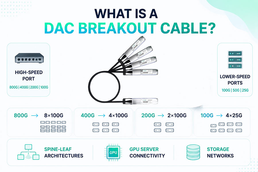
With the rapid development of AI data centers, cloud computing, and high-speed Ethernet, more and more switches now provide 400G and 800G high-speed ports, while the server side still widely deploys 100G, 50G, and even 25G networks.
To provide compatibility between devices operating at different speeds, DAC (Direct Attach Copper) products have evolved beyond standard direct-attach cables to include Breakout DAC cables.800G 400G 200G 100G AOC/DAC/AEC/ACC Cable丨C-LIGHT
The primary purpose of a Breakout DAC is to split one high-speed port into multiple lower-speed ports, maximizing port utilization.
For example:
800G → 8 × 100G
400G → 4 × 100G
200G → 2 × 100G
100G → 4 × 25G
This solution is widely used in Spine-Leaf architectures, GPU server connectivity, and storage networks.
2. What Do CR1, CR2, CR4, and CR8 Mean?
In DAC products, you will often see designations such as CR1, CR2, CR4, and CR8.
Here, CR stands for Copper Reach, referring to the physical copper cable lanes, while the number indicates the number of electrical lanes.
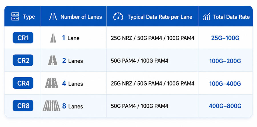
Therefore:
200G QSFP56 DAC typically belongs to CR4, while 200G QSFP112 DAC belongs to CR2.
400G DAC typically belongs to CR4.
800G DAC typically belongs to CR8.
The number of lanes determines the available breakout configurations.
3. Why Does the Industry Mainly Adopt Rate-Matched Breakout?
Today, the vast majority of DAC breakout solutions follow one fundamental principle:
The total bandwidth remains unchanged, while only the lane resources are redistributed.
For example:
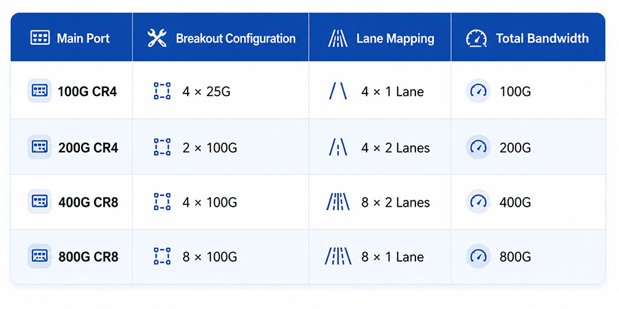
The main advantages include:
No data rate conversion
No retimer required
No protocol conversion
PHY only remaps the electrical lanes
Lowest latency
Lowest cost
Lowest power consumption
For these reasons, this is also the breakout method recommended by IEEE Ethernet standards.
4. Are There Non-Rate-Matched Breakout Solutions?
The answer is yes, but they are extremely uncommon.
In the industry, what is often referred to as a "non-rate-matched" breakout is generally not a true data rate conversion. Instead, it refers to differences in connector form factors and internal lane mapping.
For example, the Arista Active DAC solution that converts 400G QSFP-DD to 4 × QSFP28 DAC is a typical example.
Many engineers initially wonder how a QSFP-DD interface can be split into QSFP28 connectors.
In reality, the QSFP28 PCB design integrates a dedicated Gearbox (essentially a DSP processor), which converts the incoming 2 × 50G PAM4 signals from the QSFP-DD side into 4 × 25G NRZ signals at the QSFP28 interface. This enables signal conversion while maintaining the optical port protocol compatibility. The overall bandwidth remains 400G = 4 × 100G.
Therefore, it is still considered a Rate-Matched Breakout.
It is not a true bandwidth conversion such as:
400G → 4 × 40G
400G → 4 × 25G
400G → 2 × 200G + 4 × 25G
These would represent genuine rate conversion rather than standard breakout.
5. C-LIGHT DAC Breakout Solutions
To support different network architectures, C-LIGHT provides a complete portfolio of DAC Breakout products,
800G/400G/200G/100G/50G/40G/25G/10G DAC Cable丨C-LIGHT
including:
100G QSFP28 → 4 × 25G SFP28
200G QSFP56 → 2 × 100G QSFP56 or 4 × 50G SFP56
400G QSFP56-DD → 4 × 100G QSFP56 or 2 × 200G QSFP56
800G OSFP112 / QSFP-DD112 → 8 × 100G QSFP112 or 4 × 200G QSFP112
400G OSFP56 → 2 × 200G QSFP56
Custom vendor coding EEPROM and ID support
Custom lane mapping, cable colors (black, brown, red, orange, yellow, green, purple, gray, pink, white), and pull-tab colors
Multiple wire gauges (26 AWG, 28 AWG, 30 AWG)
Custom cable lengths and label colors
These solutions meet the deployment requirements of AI data centers, cloud computing, high-performance storage, and enterprise networks.
6. Conclusion
The core design principle of DAC breakout is always based on lane resource redistribution.
CR1, CR2, CR4, and CR8 not only represent the number of copper lanes but also determine how many lower-speed ports can be split from a high-speed interface. Most industry-standard breakout solutions follow the principle of maintaining the same total bandwidth, providing the lowest latency, lowest power consumption, and the best compatibility.
7、Frequently Asked Questions (FAQ)
Q1: What do CR1, CR2, CR4, and CR8 represent in DAC cables?
CR1, CR2, CR4, and CR8 represent the number of Copper Reach (CR) lanes in a Direct Attach Copper (DAC) cable. They indicate the electrical lane configuration and determine the breakout capability of the cable.
Key definitions include:
CR1: Single-lane copper connection
CR2: Two-lane copper connection
CR4: Four-lane copper connection
CR8: Eight-lane copper connection
These lane configurations define how high-speed electrical signals are transmitted between switches, servers, and networking devices.
Q2: Do all DAC cables support breakout applications?
No. Not all DAC cables support breakout functionality. A successful breakout connection requires compatibility between the switch ASIC, interface type, cable lane mapping, and network configuration.
Breakout support depends on:
Switch port capability
ASIC breakout support
DAC cable lane configuration
Transceiver or connector compatibility
Network operating system support
When all components are properly matched, DAC breakout cables can efficiently connect high-speed ports to multiple lower-speed interfaces.
Q3: What is the difference between an Arista Breakout DAC and a standard DAC?
The main difference between an Arista Breakout DAC and a standard DAC is not the physical transmission technology, but the compatibility optimization for specific networking platforms.
Key differences include:
Vendor-specific EEPROM coding
Optimized lane mapping
Platform compatibility with Arista EOS switches
Validated interoperability with specific network devices
These optimizations help ensure reliable recognition and operation in Arista-based data center environments.
Q4: Are there true non-rate-matched DAC breakout solutions?
Standard passive DAC cables generally do not support true rate conversion between different interface speeds. A passive DAC only provides electrical connectivity and does not perform signal processing or protocol conversion.
For applications requiring different output rates, solutions may include:
Active Copper Cable (ACC)
Active Electrical Cable (AEC)
Retimer-based solutions
Gearbox functionality
Network switching ASIC processing
For example, converting a 400G port into mixed-speed outputs such as 100G and 25G interfaces usually requires active electronics rather than a standard passive DAC cable.
 >
>

 >
>
 >
>
 >
>
 >
>
 >
>
 >
>
 >
>