TEL:+86 132 6656 7067


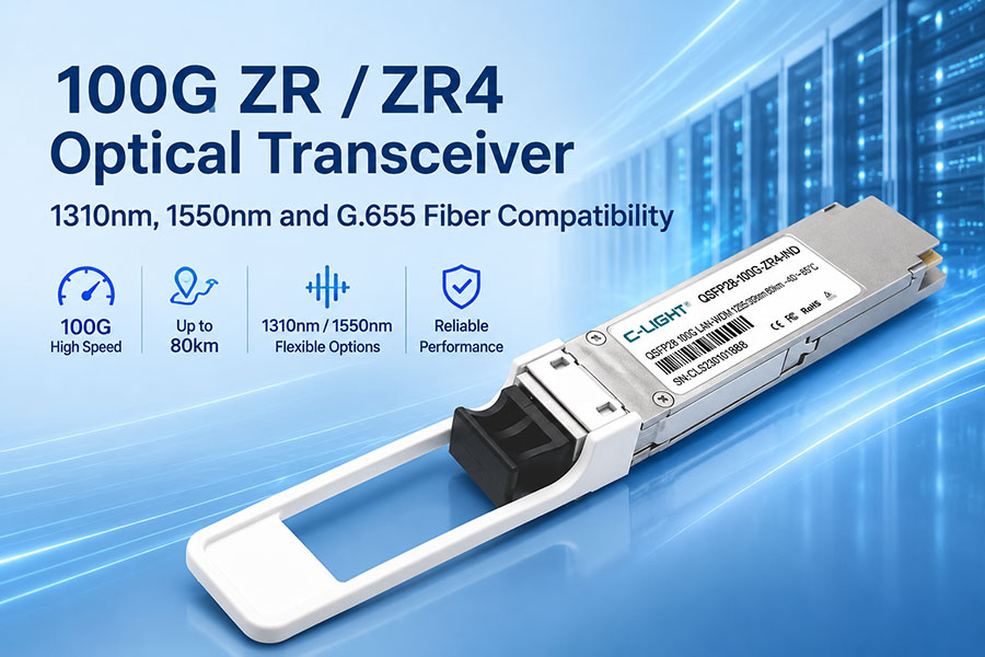
Long-distance 100G optical links require more than a nominal transmission-distance rating. The optical architecture, wavelength plan, fiber dispersion, insertion loss, receiver sensitivity, and host-side FEC configuration all affect link performance.
A common question in 100G ZR deployments is whether a module operating around 1310nm can be reconfigured to 1550nm when the installed route uses G.655 fiber. The answer depends first on the exact type of 100G ZR transceiver. In particular, a 100GBASE-ZR4 module and a coherent long-reach optical module should not be treated as interchangeable designs.
1. What Does 100G ZR Mean?
The term 100G ZR is used in the optical networking market to describe long-reach 100G optical solutions. However, the ZR label alone does not identify every technical detail of a transceiver. Different products may use different optical architectures, modulation formats, wavelengths, host interfaces, and distance specifications.
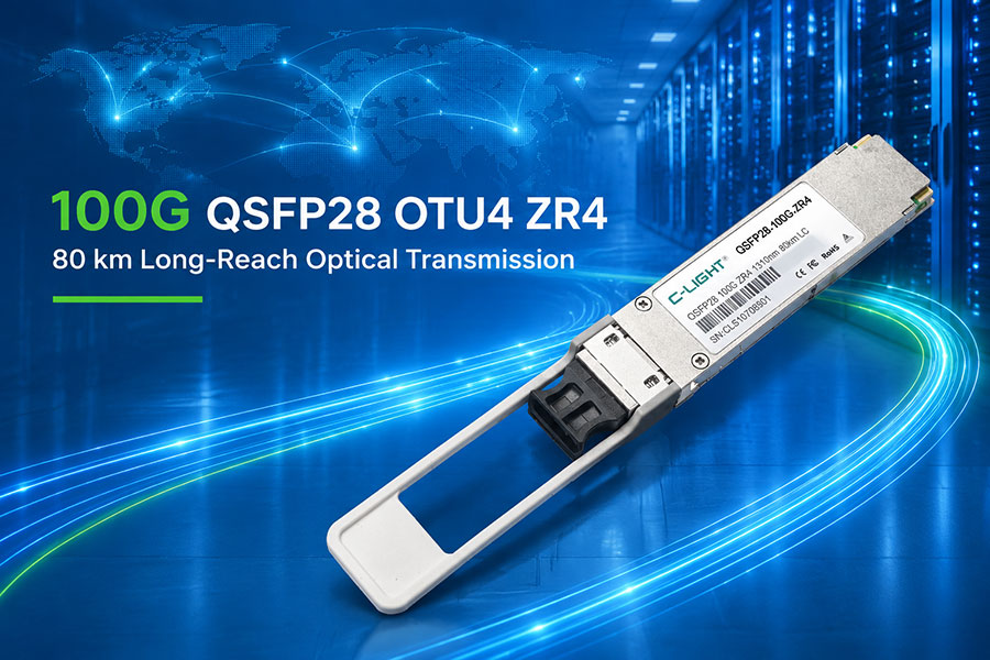
One important product category is 100G ZR4, commonly implemented in a QSFP28 form factor. A typical 100G ZR4 design uses four optical channels, each operating at approximately 25.78Gb/s. The four channels are multiplexed for transmission over single-mode fiber.
100G ZR4 is not the same as a single-channel 1550nm coherent transceiver.
A typical 100G ZR4 module uses four LAN-WDM wavelengths in the O-band, generally described as a 1310nm-class optical interface. Coherent transport products may use different optical technologies and wavelength ranges. The complete part number and datasheet are therefore essential when identifying a customer's 100G ZR module.
2. How 100G ZR4 Uses 1310nm Optical Wavelengths
A typical 100GBASE-ZR4 transceiver uses four LAN-WDM optical channels. Although the product is often described as a 1310nm module, the transmitter does not operate on only one wavelength. Each optical lane has its own nominal wavelength.
| Optical Lane | Nominal Wavelength | Typical Data Rate | Optical Band |
|---|---|---|---|
| Lane 1 | 1295.56nm | 25.78Gb/s | O-band / LAN-WDM |
| Lane 2 | 1300.05nm | 25.78Gb/s | O-band / LAN-WDM |
| Lane 3 | 1304.58nm | 25.78Gb/s | O-band / LAN-WDM |
| Lane 4 | 1309.14nm | 25.78Gb/s | O-band / LAN-WDM |
The four channels provide an aggregate data rate of approximately 100Gb/s. A typical ZR4 implementation uses NRZ modulation and a duplex LC optical interface. Some extended-reach ZR4 designs also integrate an optical amplifier, such as an SOA, to support their specified link distance.
Depending on the implementation, 100G ZR4 products may specify a reach of up to 80km over single-mode fiber. This distance is a product-level reach rating, not a guarantee that every 80km fiber route will work. Actual reach depends on the optical power budget, fiber characteristics, connector and splice losses, dispersion performance, and FEC requirements.
3. Can a 100G ZR4 Module Be Changed from 1310nm to 1550nm?
Changing the identification information stored in a transceiver's EEPROM does not change the physical wavelength emitted by its laser. The actual optical signal is determined by the transmitter's optical components and design, including the laser source and associated optical circuitry.
For a conventional 100G ZR4 module, the four LAN-WDM channels are designed around their specified O-band wavelengths. Rewriting a wavelength description or vendor information in the EEPROM cannot convert those optical channels into 1550nm channels.
A wavelength-tunable optical module is a different case. It must contain a tunable optical source and explicitly support the required tuning range. Even then, the supported configuration must be confirmed in the manufacturer's datasheet and operating instructions.
Practical distinction: EEPROM coding and optical wavelength tuning are different functions. Do not treat a software identification change as a physical wavelength conversion.
4. 100G ZR4 at 1310nm vs. 1550nm: What Changes?
The 1310nm and 1550nm wavelength regions have different transmission characteristics. The appropriate choice depends on the optical transceiver architecture and the installed fiber, rather than on the ZR label alone.
| Consideration | 100G ZR4 O-band Design | 1550nm-Class Optical Design |
|---|---|---|
| Typical wavelength region | Four LAN-WDM channels around 1295–1309nm | Approximately 1550nm or a specified C-band channel |
| Optical architecture | Commonly four-lane NRZ transmission | Depends on the product; may use single-channel or coherent technology |
| Fiber characteristics | Evaluate attenuation and dispersion across the specified O-band channels | Evaluate the fiber's attenuation and dispersion in its specified C-band range |
| Wavelength adjustment | Fixed LAN-WDM channels in a conventional ZR4 module | May be fixed or tunable, depending on the module design |
| Interoperability | Requires matching ZR4 specifications and host configuration | Requires matching wavelength, modulation, line interface, and system design |
A 1550nm module is not automatically a replacement for a 1310nm ZR4 module. The two products may differ in modulation, optical power, receiver design, dispersion tolerance, connector interface, and host-side requirements. Both link endpoints must support the same optical transmission system.
5. Is 100G ZR4 Compatible with G.655 Fiber?
ITU-T G.655 defines non-zero dispersion-shifted single-mode optical fiber. Its dispersion characteristics are specified particularly for the 1530–1565nm wavelength region, making the fiber useful in systems operating in that part of the spectrum. The exact characteristics vary by G.655 category and fiber design.
This does not mean that every G.655 cable is automatically incompatible with a 1310nm 100G ZR4 module. It also does not mean that a module designed for 1310nm operation can automatically be deployed on every G.655 route. The fiber's actual attenuation, dispersion characteristics at the operating wavelengths, and the transceiver's specified tolerances must be considered together.
For a 100G ZR4 link, the four O-band wavelengths must be evaluated against the actual fiber characteristics. A fiber's G.655 designation alone does not provide all the information required to approve a specific 100G ZR4 application.
Information required for a compatibility assessment:
The exact G.655 fiber category or manufacturer's cable specification.
Attenuation values at the ZR4 operating wavelengths.
Chromatic dispersion data across the relevant wavelength range.
Total route length, connector count, splice count, and measured insertion loss.
The exact 100G ZR4 module model and its optical operating limits.
6. Evaluating 42km, 35km, and 30km 100G Links
In the customer scenario, three optical routes have lengths of 42km, 35km, and 30km. These distances are all below the nominal 80km reach specified by some 100G ZR4 products. However, route length alone cannot confirm that the links will operate reliably.
| Link | Reported Distance | Items to Verify |
|---|---|---|
| Link A | 42km | End-to-end insertion loss, dispersion, connector and splice condition, FEC settings |
| Link B | 35km | Actual fiber attenuation, optical power levels, route events, host compatibility |
| Link C | 30km | Optical budget, receiver margin, connector condition, module operating limits |
A 42km route may have more optical loss than another route of greater length if it contains more connectors, splices, patch panels, or damaged sections. Each link should therefore be measured independently.
7. FEC, Optical Power, and Link Testing
7.1 Verify the FEC Configuration
Forward Error Correction helps the receiving system recover data affected by transmission errors. Some 100G ZR4 products specify host-side RS-FEC as a requirement for their rated reach. Other products may have different requirements. The module datasheet and the switch or router documentation must be checked together.
FEC should not be enabled or disabled based only on the generic ZR or ZR4 name. The exact module specification, host platform, port configuration, and supported FEC mode determine the correct setting.
7.2 Check DDM / DOM Parameters
Digital Diagnostic Monitoring can provide useful operating data when supported by the transceiver and host platform. Typical readings include:
Transmitter optical power (Tx Power).
Receiver optical power (Rx Power).
Module temperature.
Supply voltage.
Laser bias current, when available.
Compare the Tx and Rx readings with the limits in the module datasheet. DDM can help identify abnormal optical levels, but it does not independently measure the complete route insertion loss or locate a specific fiber fault.
7.3 Use an Optical Power Meter and OTDR
An optical light source and power meter, or an optical loss test set, can measure end-to-end insertion loss at the relevant wavelength. This is important when checking whether a long-distance link stays within the module's optical budget.
An OTDR can help identify fiber length, splice events, connector events, localized loss, and possible breaks. For a complete assessment, OTDR results should be interpreted alongside end-to-end insertion-loss measurements and the module's optical specifications.
8. Information to Confirm Before Replacing a 100G ZR Module
Before deciding whether a 1310nm module should be replaced with a 1550nm model, collect the following information:
Exact part number: Confirm the complete model and manufacturer, not just the description "100G ZR SFP."
Form factor: Verify whether the equipment uses QSFP28 or another 100G interface.
Optical specification: Confirm whether the product is 100GBASE-ZR4, a coherent module, or another proprietary long-reach design.
Wavelength plan: Check the actual Tx and Rx wavelengths, including all four LAN-WDM channels where applicable.
FEC support: Confirm the required FEC mode on both connected devices.
Fiber data: Obtain the G.655 category, measured attenuation, dispersion information, and route loss.
Host compatibility: Confirm port support, firmware requirements, and optical module compatibility.
For the three reported links of 42km, 35km, and 30km, the same checks should be completed separately. A successful result on one route does not establish that the other two routes have identical optical conditions.
9. Conclusion
100G ZR is a product category that requires more precise identification before wavelength or fiber compatibility can be assessed. A typical 100G ZR4 module uses four LAN-WDM channels around 1310nm and is fundamentally different from a single-channel or coherent 1550nm optical design.
Changing EEPROM identification data cannot convert a fixed-wavelength ZR4 transmitter into a 1550nm transmitter. A wavelength change is possible only when the optical hardware is specifically designed to support the required tuning range.
G.655 fiber compatibility should be assessed using the actual fiber category, wavelength-dependent attenuation and dispersion, measured route loss, and the transceiver's operating specifications. For 42km, 35km, and 30km links, independent optical measurements and FEC verification are more reliable than making a decision from distance or fiber designation alone.
To confirm a suitable 100G ZR or ZR4 solution for a specific network, provide the module part number, equipment model, fiber specification, and measured link parameters. Contact C-LIGHT for technical assistance.
 >

 >
 >
 >
 >
 >
 >
 >