TEL:+86 132 6656 7067


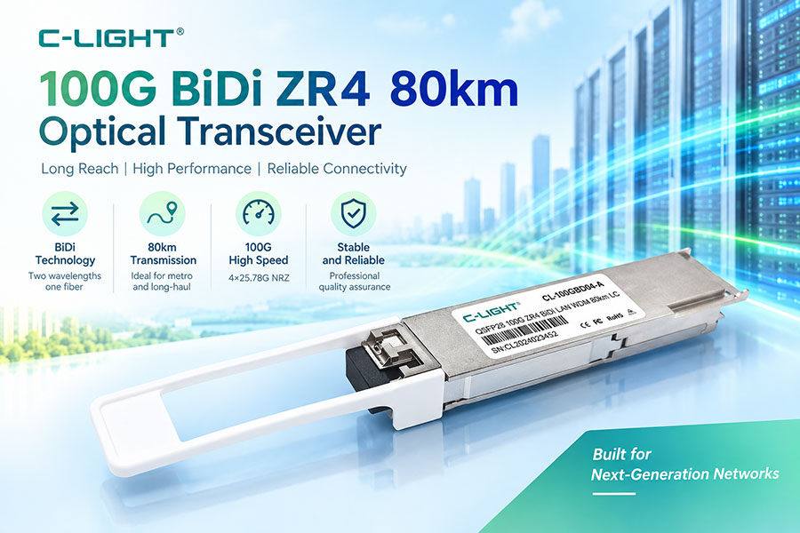
The C-LIGHT CLOTU4QSFPZR4 is a QSFP28 optical transceiver designed for 100G/OTU4 ZR4 point-to-point links over single-mode fiber. With a specified reach of up to 80 km and host-side KR4 forward error correction (FEC) enabled, it provides long-distance 100G connectivity for telecommunications transport, metro networks, and high-capacity optical infrastructure.
The module combines four LAN-WDM wavelength channels with an EML optical transmitter and an SOA+PIN receiver. Its duplex LC interface connects separate transmit and receive fiber paths, while the QSFP28 package integrates the optical components and high-speed electrical interface into a compact transceiver.
Operating from a single 3.3 V supply, the CLOTU4QSFPZR4 has a maximum power consumption of 5.5 W and supports a case temperature range of 0°C to +70°C. Digital diagnostic monitoring helps network operators monitor available module operating parameters and maintain long-reach optical connections.
1. Product Overview and Key Features
The CLOTU4QSFPZR4 is designed for long-reach 100G Ethernet and OTU4 applications where compatible network equipment must communicate over extended single-mode fiber links. Its LAN-WDM architecture combines four optical channels within the module, while the duplex LC connector provides independent transmit and receive paths.
Key Features
100G/OTU4 connectivity: Designed for 100G/112GBASE-ZR4 point-to-point Ethernet links.
80 km transmission reach: Supports long-distance single-mode fiber links with host-side KR4 FEC enabled for the specified reach.
Four LAN-WDM wavelengths: Uses wavelength channels centered around 1295.56 nm, 1300.05 nm, 1304.58 nm, and 1309.14 nm.
EML laser transmission: Uses an electro-absorption modulated laser for high-speed optical signaling.
SOA+PIN receiver: Combines a semiconductor optical amplifier with a PIN photodiode receiver.
Duplex LC interface: Supports separate transmit and receive fiber paths over single-mode fiber.
QSFP28 form factor: Designed for compatible switches, routers, and optical transport equipment.
Digital diagnostics: Provides a two-wire serial interface with digital diagnostic monitoring.
Low-voltage power design: Uses a single +3.3 V supply with maximum power consumption of 5.5 W.
Operating temperature: Supports case temperatures from 0°C to +70°C.
2. Technical Specifications
| Parameter | Specification |
|---|---|
| Product model | CLOTU4QSFPZR4 |
| Form factor | QSFP28 |
| Application | 100GE / OTU4 |
| Data rate listed in datasheet | 100G / 112G |
| Optical application | 100G/112GBASE-ZR4 point-to-point Ethernet links |
| Maximum transmission distance | Up to 80 km over single-mode fiber with host-side KR4 FEC enabled |
| Optical architecture | Four-lane LAN-WDM |
| Transmitter | LAN-WDM EML laser |
| Receiver | SOA+PIN |
| Optical connector | Duplex LC |
| Electrical interface | CAUI-4, compliant with IEEE 802.3bm-2015 as specified in the datasheet |
| Power supply | Single +3.3 V |
| Maximum power consumption | 5.5 W |
| Operating case temperature | 0°C to +70°C |
| Digital management | Two-wire serial interface with digital diagnostic monitoring |
| QSFP28 standards | SFF-8661 Rev. 2.5 and SFF-8636 Rev. 2.10a |
| RoHS compliance | Complies with EU Directive 2011/65/EU, as listed in the datasheet |
| Laser classification | Class 1 |
3. Four-Lane LAN-WDM Optical Design
The CLOTU4QSFPZR4 uses four LAN-WDM wavelengths to carry optical data. Each channel operates within a defined wavelength range, allowing the four optical lanes to be multiplexed within the transceiver and transmitted through the optical interface.
LAN-WDM supports high-capacity transmission by combining multiple wavelength channels within a defined optical spectrum. The duplex LC interface uses one fiber for transmission and another for reception, making the module suitable for conventional duplex single-mode fiber infrastructure where the optical link meets the specified budget.
LAN-WDM Wavelength Specifications
| Optical Lane | Minimum Wavelength | Typical Wavelength | Maximum Wavelength |
|---|---|---|---|
| L0 | 1294.53 nm | 1295.56 nm | 1296.59 nm |
| L1 | 1299.02 nm | 1300.05 nm | 1301.09 nm |
| L2 | 1303.54 nm | 1304.58 nm | 1305.63 nm |
| L3 | 1308.09 nm | 1309.14 nm | 1310.19 nm |
The wavelength arrangement enables four optical channels to operate through the module's LAN-WDM interface. During deployment, the far-end equipment must support a compatible optical application, and the installed fiber path must maintain suitable insertion loss and received optical power.
Duplex LC connector cleanliness and correct fiber polarity are particularly important on long-reach links. Inspecting connectors and testing the completed path helps identify excessive loss before service activation.
4. Transmitter Optical Performance
The module uses an EML-based LAN-WDM transmitter. Its optical specifications cover wavelength control, launch power, extinction ratio, and signal quality across the four lanes.
| Parameter | Symbol | Minimum | Typical | Maximum | Unit |
|---|---|---|---|---|---|
| Side-mode suppression ratio | SMSR | 30 | — | — | dB |
| Total average optical launch power | POUT | — | — | 12.5 | dBm |
| Average launch power per lane | POUTL | 2 | — | 6.5 | dBm |
| Average launch power with transmitter disabled, per lane | POUT_OFF | — | — | -30 | dBm |
| Extinction ratio at 28.05 Gbps | ER | 8 | — | — | dB |
| Spectral width | Δλ | — | — | 1 | nm |
| Optical modulation amplitude per lane | OMA | 2.5 | — | 7 | dBm |
| Transmitter and dispersion penalty per lane | TDP | — | — | 2.2 | dB |
| OMA minus TDP per lane | OMA-TDP | 1.5 | — | — | dBm |
| Maximum OMA launch-power difference between lanes | DT_OMA | — | — | 4 | dB |
| Optical return-loss tolerance | ORLT | — | — | 20 | dB |
| Relative intensity noise | RIN20OMA | — | — | -130 | dB/Hz |
| Transmitter reflectance | TR | — | — | -26 | dB |
These parameters characterize the transmitted optical signal and the consistency of the four lanes. Link engineering should evaluate transmitter limits together with receiver sensitivity, fiber attenuation, connector losses, and the required operating distance.
5. Receiver Sensitivity and 80 km Transmission
The receiver uses an SOA+PIN architecture and is designed for the module's long-reach optical application. The datasheet specifies receiver sensitivity values for two lane-rate conditions, along with receive-power limits and loss-of-signal thresholds.
| Parameter | Symbol | Specified Value | Unit |
|---|---|---|---|
| Receiver sensitivity, OMA per lane at 25.78G | — | -27.5 | dBm |
| Receiver sensitivity, OMA per lane at 27.95G | — | -25 | dBm |
| Stressed receiver J2 jitter per lane | — | 0.33 | UI |
| Stressed receiver J9 jitter per lane | — | 0.48 | UI |
| Vertical eye closure penalty | — | 2 | dB |
| Receiver damage threshold | Pin, damage | -2.5 | dBm |
| Average receive power per lane | — | -28 to -5 | dBm |
| Receive power in OMA per lane, overload limit | OMA | -4.5 maximum | dBm |
| Receiver reflectance | RXR | -26 maximum | dB |
| Loss-of-signal assert threshold | LOSA | -40 minimum | dBm |
| Loss-of-signal de-assert threshold | LOSD | -30 maximum | dBm |
| Loss-of-signal hysteresis | LOSH | 0.5 minimum | dB |
The datasheet specifies receiver sensitivity of -28 dBm with host-side KR4 FEC enabled for links up to 80 km over single-mode fiber. The separate lane-rate sensitivity figures above are listed under their stated measurement conditions.
KR4 FEC and Link Budget
Host-side KR4 forward error correction is required for the specified 80 km reach. FEC provides error-correction capability that helps the optical link meet its required bit-error performance under the supported operating conditions.
Before deployment, confirm that both the host platform and port configuration support the required FEC mode. The optical budget must also account for fiber attenuation, connector insertion loss, splices, patch panels, and other losses along the route.
Even when the physical path is shorter than 80 km, the received optical power must remain within the transceiver's supported operating range. Measuring insertion loss and checking received power at both ends helps establish whether the completed link meets the design requirements.
6. QSFP28 Interface, Power, and Digital Monitoring
Electrical Interface and Equipment Compatibility
The CLOTU4QSFPZR4 uses the QSFP28 form factor and a CAUI-4 electrical interface. Its datasheet lists compliance with SFF-8661 Rev. 2.5, SFF-8636 Rev. 2.10a, and IEEE 802.3bm-2015 for the electrical interface.
The host switch, router, or optical transport system must support the intended 100GE/OTU4 application, the module's electrical interface, and KR4 FEC operation. Mechanical fit alone does not guarantee compatibility. Check the equipment's supported optical modules, firmware requirements, port configuration, and operating modes before ordering.
Power and Thermal Requirements
The module operates from a single +3.3 V supply and has maximum power consumption of 5.5 W. Its specified case operating temperature range is 0°C to +70°C.
When installing multiple high-speed modules, verify the host's available power budget and airflow. Thermal performance depends on the module population, chassis design, ambient temperature, and cooling configuration.
Digital Diagnostic Monitoring
The module provides a two-wire serial interface with digital diagnostic monitoring. Supported information can help network teams review operating conditions and investigate optical link issues, subject to the diagnostic fields exposed by the module and host system.
During commissioning, verify that the module is correctly recognized and review available temperature, optical power, and alarm information. Recording baseline values provides a useful reference for subsequent troubleshooting and maintenance.
7. Applications for 80 km 100G ZR4 Optics
Telecommunications and Metro Transport
Telecommunications networks often require high-capacity connections between aggregation sites, transport facilities, and remote network nodes. The CLOTU4QSFPZR4 provides a 100G-class optical interface for compatible point-to-point links of up to 80 km, subject to the required FEC configuration and optical budget.
Data Center Interconnections
Where data center locations or aggregation points are separated by substantial distances, short-reach optical modules may not meet the required reach. The CLOTU4QSFPZR4 is designed for longer single-mode fiber paths and can be considered for suitable 100G Ethernet interconnections.
Enterprise and Service Provider Backbones
Enterprise and service provider networks use long-distance optical links to connect distributed facilities, regional aggregation equipment, and backbone nodes. The module's QSFP28 package and duplex LC interface support integration into compatible equipment designed for the specified optical application.
OTU4 and 100G Ethernet Transport
The product datasheet lists 100GE/OTU4 as the application and 100G/112G as the data-rate designation. Host platform documentation should be checked to confirm support for the target Ethernet or transport interface, including FEC and port operating requirements.
8. Installation and Deployment Requirements
Reliable operation depends on compatibility between the transceiver, host platform, and complete optical path. Before installation, confirm the following:
Host support: Verify QSFP28 compatibility and support for the intended 100GE/OTU4 ZR4 application.
FEC configuration: Enable host-side KR4 FEC for the specified 80 km reach.
Fiber suitability: Use single-mode fiber with sufficient optical margin for the full route.
Optical loss: Account for fiber attenuation, connectors, splices, and patch panels in the link budget.
Connector condition: Inspect and clean duplex LC connectors before connection.
Received power: Ensure the received optical levels remain within the specified operating limits.
Power and cooling: Confirm adequate host power, airflow, and operating temperature.
Diagnostic status: Review the available module monitoring information and interface alarms.
After installation, check link status, port configuration, FEC operation, optical levels, and error counters. For production links, acceptance testing should reflect the network's performance requirements and the criticality of the connection.
9. Conclusion
The C-LIGHT CLOTU4QSFPZR4 is a QSFP28 100G/OTU4 ZR4 optical transceiver designed for point-to-point transmission over single-mode fiber at distances of up to 80 km. Its four LAN-WDM wavelengths, EML laser, SOA+PIN receiver, duplex LC connector, and digital diagnostic monitoring support long-reach optical transport in compatible network platforms.
With maximum power consumption of 5.5 W and an operating case temperature range of 0°C to +70°C, the module is designed for equipment that meets its electrical and thermal requirements. The specified 80 km reach requires host-side KR4 FEC, an appropriate optical loss budget, and compatible equipment at both ends.
For telecommunications transport, metro networks, long-distance data center interconnections, and enterprise backbones, the CLOTU4QSFPZR4 offers a high-capacity optical interface where 100G-class connectivity and extended single-mode fiber reach are required.
 >
>

 >
>
 >
>
 >
>
 >
>
 >
>
 >
>
 >
>