TEL:+86 132 6656 7067


Optical transceiver design increasingly relies on advanced photonic integration and efficient semiconductor laser technologies. As data center links move toward 400G, 800G, and 1.6T, manufacturers must balance optical performance, power consumption, integration density, manufacturing complexity, and thermal management.
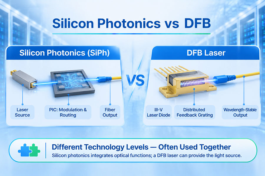
Silicon photonics (SiPh) and distributed feedback (DFB) lasers are both important in this development, but they serve different functions. Silicon photonics provides a platform for integrating optical components such as waveguides, modulators, multiplexers, and photodetectors. DFB is a semiconductor laser architecture that generates light with a selected wavelength and stable single-mode operation.
Rather than treating them as mutually exclusive alternatives, it is more useful to examine how each technology contributes to an optical transceiver and how their different implementations affect performance, packaging, and system design.
1. What Is Silicon Photonics?
Silicon photonics is an integrated photonic technology that uses silicon-based semiconductor manufacturing processes to build optical circuits. It combines multiple optical functions on a photonic integrated circuit (PIC), reducing the need for numerous separately packaged optical components.
A silicon photonics chip can integrate several important functions:
Optical waveguides: Guide light between different components on the photonic chip.
Mach-Zehnder modulators (MZMs): Encode electrical data onto an optical carrier by controlling the interference of optical signals.
Ring resonators: Provide wavelength-selective filtering or modulation functions in suitable designs.
Optical multiplexers and demultiplexers: Combine or separate multiple wavelength channels.
Photodetectors: Convert incoming optical signals into electrical signals, commonly using germanium-based structures integrated with silicon photonics.
One important material limitation is that standard silicon is not an efficient light emitter because of its indirect bandgap. Therefore, silicon photonics systems generally require a separate laser source or an integrated laser made from a suitable light-emitting semiconductor material.
In many data center transceiver designs, an indium phosphide (InP) continuous-wave laser supplies light to the silicon photonic chip. The silicon PIC then performs optical modulation, routing, and wavelength multiplexing.
2. What Is a DFB Laser?
A Distributed Feedback (DFB) laser is a semiconductor laser that uses a periodic grating structure to provide optical feedback along the laser cavity. The grating selects the operating wavelength and supports stable single-longitudinal-mode emission.
DFB lasers are widely used in optical communications because they can provide controlled wavelengths, suitable output power, and narrow spectral characteristics for fiber-optic transmission.
Common DFB laser characteristics include:
Single-mode operation: The grating helps select a dominant longitudinal mode.
Wavelength control: The grating design determines the nominal emission wavelength, while temperature and operating conditions influence its actual value.
Direct modulation capability: Some DFB lasers can be modulated by varying the injection current.
Continuous-wave operation: DFB lasers can also provide an unmodulated optical carrier for use with an external modulator.
Compact semiconductor construction: DFB devices can be packaged as discrete laser components or integrated into more complex optical assemblies.
DFB lasers are commonly manufactured using III-V semiconductor materials such as indium phosphide for communication wavelengths around 1310 nm and 1550 nm.
3. Silicon Photonics vs DFB: Different Technology Levels
The most important distinction is that silicon photonics describes an optical integration platform, whereas DFB describes a laser structure. A silicon photonics transceiver can use a DFB laser as its light source, so the two technologies can operate together in the same optical system.
| Technical Factor | Silicon Photonics | DFB Laser |
|---|---|---|
| Technology category | Photonic integration platform | Semiconductor laser architecture |
| Primary function | Integrates and processes optical signals | Generates optical signals |
| Typical material | Silicon-based photonic circuits | III-V semiconductor materials, commonly InP |
| Light generation | Usually requires a separate or integrated suitable laser source | Generates light directly |
| Optical modulation | Can integrate MZMs and other modulators | Can support direct modulation or provide continuous-wave light for external modulation |
| Integration approach | Multiple optical functions on a PIC | Laser device with a distributed feedback grating |
| Wavelength control | Depends on the laser source and photonic circuit design | Determined by the grating and operating conditions |
| Typical role in a transceiver | Optical engine, modulation, routing, and multiplexing | Optical source |
| Compatibility | Can be combined with DFB and other suitable laser sources | Can operate as a discrete source or be integrated with other photonic components |
Consequently, comparing the power consumption or transmission distance of silicon photonics and DFB without specifying the complete transceiver architecture can be misleading. Those characteristics depend on the laser, modulator, receiver, DSP, optical interface, and packaging design.
4. How DFB Lasers Work with Silicon Photonics
One widely used integration approach combines a DFB laser with a silicon photonic integrated circuit. The DFB provides a continuous-wave optical carrier, while the silicon photonic chip performs data modulation and optical signal routing.
A simplified signal path is:
DFB laser: Generates a continuous-wave optical signal at the required wavelength.
Optical coupling: Transfers the laser output into the silicon photonic chip.
Silicon photonic modulator: Encodes electrical data onto the optical carrier.
Optical multiplexer: Combines multiple wavelength channels when required by the architecture.
Fiber interface: Couples the modulated optical signal into the transmission fiber.
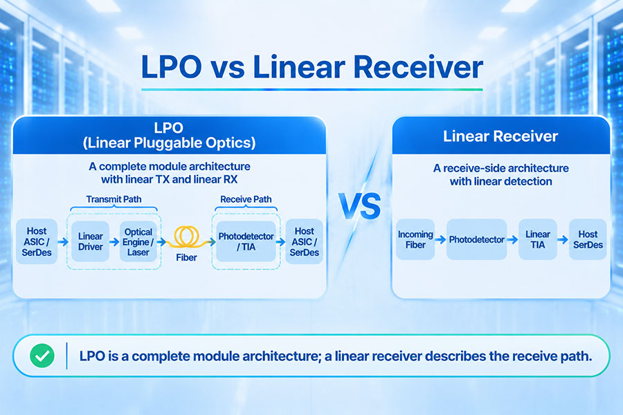
On the receive side, the optical signal enters the silicon photonic receiver, where waveguides and other optical structures route the signal toward photodetectors. The photodetectors convert the optical signal into electrical signals, which are then processed by the receiver electronics.
This division of functions allows laser generation and photonic integration to be optimized separately. It also creates additional engineering requirements for optical coupling, alignment, thermal management, and laser stability.
5. DFB Laser Integration Methods in Silicon Photonics
Silicon photonics requires a suitable optical source. There are several ways to combine a laser with a silicon photonic circuit, each with different packaging, thermal, and manufacturing considerations.
External Laser Source
An external laser source (ELS) is positioned separately from the silicon photonic chip or optical engine. The laser supplies continuous-wave light through an optical connection.
This approach separates the heat-generating laser from the photonic chip and can simplify laser replacement or maintenance in certain system architectures. However, it introduces additional optical interfaces and coupling considerations.
Hybrid Integration
Hybrid integration combines a III-V laser chip, such as an InP DFB, with a silicon photonic chip in a shared package or assembly. Optical coupling may use techniques such as butt coupling, flip-chip attachment, or photonic wire bonding.
This approach can reduce the physical separation between the laser and photonic circuit while retaining the light-generation capability of III-V semiconductor materials.
Heterogeneous Integration
Heterogeneous integration places different semiconductor materials together within a more closely integrated photonic structure. It can combine the light-emitting properties of III-V materials with the optical routing and integration capabilities of silicon.
Manufacturing precision, bonding processes, thermal behavior, and yield are important considerations for these integration methods.
| Integration Method | Laser Location | Key Advantage | Engineering Consideration |
|---|---|---|---|
| External laser source | Separate from the silicon PIC | Independent laser selection and thermal separation | Optical coupling and additional interfaces |
| Hybrid integration | Packaged alongside or attached to the PIC | Combines III-V laser and silicon photonic functions | Alignment, bonding, and assembly precision |
| Heterogeneous integration | Integrated using different semiconductor materials | Higher integration density | Material compatibility, manufacturing yield, and thermal design |
6. Directly Modulated DFB vs Continuous-Wave DFB
DFB lasers can be used in different transmitter configurations. Two important approaches are direct modulation and continuous-wave operation with an external modulator.
Directly Modulated DFB (DML)
A directly modulated laser changes its optical output in response to variations in injection current. The electrical data signal directly controls the laser output, allowing a relatively simple transmitter structure.
DML technology can reduce component count and packaging complexity in suitable applications. However, direct modulation can introduce frequency chirp, and the interaction between chirp and fiber dispersion can limit performance at higher data rates or longer distances.
Continuous-Wave DFB with External Modulation
In this configuration, the DFB laser generates a relatively constant optical carrier. A separate modulator, such as a silicon photonic Mach-Zehnder modulator, applies the data signal.
Separating light generation from data modulation provides greater flexibility in transmitter design. It is particularly relevant to silicon photonics architectures where the DFB acts as the optical source and the silicon PIC performs modulation.
| Feature | Directly Modulated DFB | CW DFB with External Modulator |
|---|---|---|
| Modulation method | Laser current modulation | External optical modulation |
| Laser operation | Optical output changes with the data signal | Laser provides a continuous optical carrier |
| External modulator | Not required for direct modulation | Required |
| Chirp behavior | Direct modulation can introduce frequency chirp | Depends on the external modulator and transmitter design |
| Integration | Can use a discrete laser transmitter design | Can be combined with a silicon photonic modulator |
| Design priority | Component simplicity and suitable reach | Modulation flexibility and photonic integration |
The choice depends on data rate, fiber distance, modulation format, optical budget, and transmitter performance requirements.
7. Optical Performance: Wavelength, Stability, and Signal Quality
Optical performance depends on the characteristics of the light source and the complete transmitter and receiver design. DFB lasers and silicon photonics contribute different capabilities to this process.
Wavelength Stability
The DFB grating selects the laser's nominal emission wavelength. However, the actual wavelength can shift with temperature and operating current. Temperature control may be required for applications with narrow wavelength spacing or demanding wavelength accuracy.
Silicon photonic circuits also have temperature-dependent behavior. For example, the resonant wavelength of a ring resonator or the phase relationship in an MZM can change with temperature. Thermal tuning and control circuits may therefore be required, depending on the design.
Optical Power and Coupling Loss
A DFB laser must provide sufficient optical power for the intended link after accounting for coupling losses and other optical components. In silicon photonics, light must be coupled efficiently from the laser into the PIC.
Coupling losses can reduce the optical power available to the transmitter and affect the overall link budget. The design must account for laser output power, coupling efficiency, modulator insertion loss, multiplexing loss, fiber attenuation, and receiver sensitivity.
Signal Quality
Signal quality depends on the laser's spectral characteristics, modulation method, optical noise, receiver performance, and transmission channel. A high-quality DFB source does not automatically guarantee a high-performance optical link, just as a silicon photonic chip does not independently determine the complete link performance.
8. Power Consumption and Thermal Management
Power consumption is an important consideration in high-density optical transceivers. Silicon photonics can integrate multiple optical functions into a compact PIC, while DFB lasers provide the optical energy required for transmission.
However, total module power depends on the complete design rather than the photonic platform or laser type alone.
Important power and thermal factors include:
Laser efficiency: Determines how much electrical power is required to generate the optical output.
Laser cooling: Temperature stabilization may be required depending on wavelength and operating conditions.
Modulator drive: Silicon photonic modulators require electrical drivers and may include thermal tuning circuits.
Optical coupling: Higher coupling loss may require greater laser output power.
Receiver electronics: TIAs, photodetectors, and associated circuits contribute to module power.
DSP and control circuitry: Signal processing and module management can contribute significantly to total power consumption.
For 400G and 800G transceivers, thermal management becomes increasingly important as the number of optical lanes and electronic components increases. Module designers must consider laser temperature, PIC tuning, driver power, receiver electronics, and overall airflow.
9. Silicon Photonics vs DFB in 400G and 800G Transceivers
High-speed transceivers use multiple optical lanes or wavelength channels to achieve aggregate data rates. Silicon photonics can integrate modulators, waveguides, and multiplexing functions into a compact optical engine, while DFB lasers can provide the optical carriers used by that engine.
For example, an 800G transmitter may use multiple optical lanes operating at high per-lane data rates. Depending on the architecture, the optical engine may use separate laser sources, multiple wavelengths, or parallel optical channels.
| Application | Silicon Photonics Role | DFB Laser Role |
|---|---|---|
| 400G DR4 | Can integrate parallel modulation and optical routing functions | Can provide optical carriers for the transmitter |
| 400G FR4 | Can integrate wavelength multiplexing and modulation | Can supply the required wavelength channels |
| 800G DR8 | Can support multi-lane optical engine integration | Can provide light for the optical lanes |
| 800G 2×FR4 | Can integrate multiple wavelength channels and multiplexing functions | Can provide continuous-wave sources for modulation |
| Coherent optical systems | Can integrate complex optical modulation and routing structures | May serve as a laser source, depending on linewidth and system requirements |
These are possible architectural roles rather than universal product implementations. Actual transceiver designs may use EMLs, DMLs, silicon photonics, or combinations of different photonic technologies.
10. Silicon Photonics vs EML: An Important Related Distinction
When evaluating optical transmitter technologies, silicon photonics is often discussed alongside EML rather than DFB alone. This is because EML and silicon photonics can both describe different approaches to optical modulation and transmitter integration.
An Electro-Absorption Modulated Laser (EML) typically integrates a DFB laser and an electro-absorption modulator on an InP-based device. The DFB section generates light, while the EAM modulates the optical signal.
A silicon photonics transmitter generally uses a silicon PIC for modulation and optical routing, with a separate or integrated suitable laser source.
| Feature | Silicon Photonics | EML |
|---|---|---|
| Technology basis | Silicon-based photonic integration | Integrated laser and electro-absorption modulator |
| Light source | External, hybrid-integrated, or integrated laser | DFB laser section |
| Modulation | Often MZM or ring-based modulation | Electro-absorption modulation |
| Integration focus | Multiple optical functions on a PIC | Laser and modulator integration |
| Engineering considerations | Laser coupling, PIC loss, tuning, and packaging | Laser performance, EAM characteristics, and thermal control |
Neither approach is universally superior. The selection depends on reach, data rate per lane, modulation requirements, optical budget, manufacturing process, and system-level power targets.
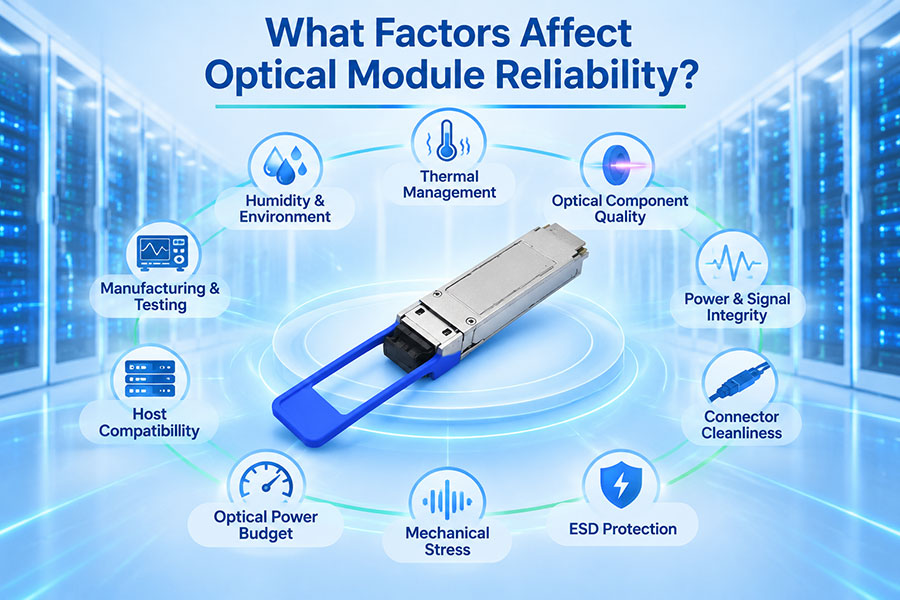
11. Reliability and Manufacturing Considerations
Reliability depends on the quality of the laser, photonic chip, optical coupling, packaging, and electronic components. Both silicon photonics and DFB-based designs have specific manufacturing challenges.
Silicon Photonics Reliability
Silicon photonics manufacturing requires precise control of waveguide dimensions, modulator structures, coupling interfaces, and photonic circuit performance. Packaging and optical alignment are especially important because coupling loss can directly affect the available optical power budget.
Thermal tuning components and control circuits must also operate reliably over the intended temperature range.
DFB Laser Reliability
DFB laser reliability depends on semiconductor material quality, operating current, junction temperature, optical feedback, packaging, and long-term aging. Laser output power and wavelength behavior should remain within the specified operating limits.
When DFB lasers are integrated with silicon photonics, the complete assembly introduces additional considerations such as bonding reliability, optical coupling stability, and thermal interaction between components.
Manufacturing validation should include optical output power, wavelength, spectral characteristics, coupling loss, receiver performance, temperature behavior, and long-term reliability testing.
12. Which Technology Is Better for Data Center Optical Transceivers?
There is no universal winner because silicon photonics and DFB perform different functions. The appropriate architecture depends on whether the design priority is photonic integration, laser performance, transmitter complexity, power efficiency, or manufacturing flexibility.
| Design Requirement | Technology to Evaluate | Reason |
|---|---|---|
| High-density photonic integration | Silicon photonics | Integrates waveguides, modulators, and optical routing |
| Stable single-mode optical source | DFB laser | Grating-based wavelength selection |
| Multiple optical functions on one chip | Silicon photonics | Supports integrated optical circuit design |
| Continuous-wave laser source | CW DFB | Provides an optical carrier for external modulation |
| Directly modulated transmitter | DML-based DFB | Electrical current directly modulates laser output |
| Compact laser and modulator integration | EML or hybrid photonic integration | Combines light generation and modulation functions |
| Flexible optical engine design | Silicon photonics with a suitable laser source | Separates laser selection from PIC functionality |
For many modern data center applications, the practical design is not silicon photonics or DFB. It is a silicon photonic engine combined with an appropriate DFB laser source, along with drivers, TIAs, control electronics, and other required components.
13. C-LIGHT Optical Transceiver Solutions for High-Speed Networks
As data center networks move toward 400G, 800G, and 1.6T connectivity, optical transceiver selection requires attention to the complete transmitter and receiver architecture. Laser type, photonic integration, modulation method, optical reach, and host compatibility all influence the final module design.
C-LIGHT provides optical transceiver and fiber connectivity products for data center, enterprise, and telecommunications applications. Relevant product categories include:
400G OSFP Optical Transceivers: High-speed optical connectivity options for compatible data center switching platforms. View 400G OSFP Products.
800G OSFP Optical Transceivers: Optical connectivity for high-bandwidth data center and AI networking applications. View 800G OSFP Products.
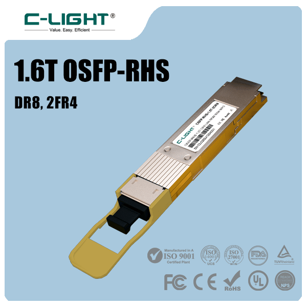
1.6T OSFP-RHS Products: Next-generation optical connectivity for compatible high-density switching platforms. View 1.6T OSFP-RHS Products.
Optical Transceiver Portfolio: Products covering multiple data rates and application requirements. Browse Optical Transceivers.
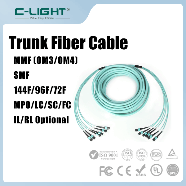
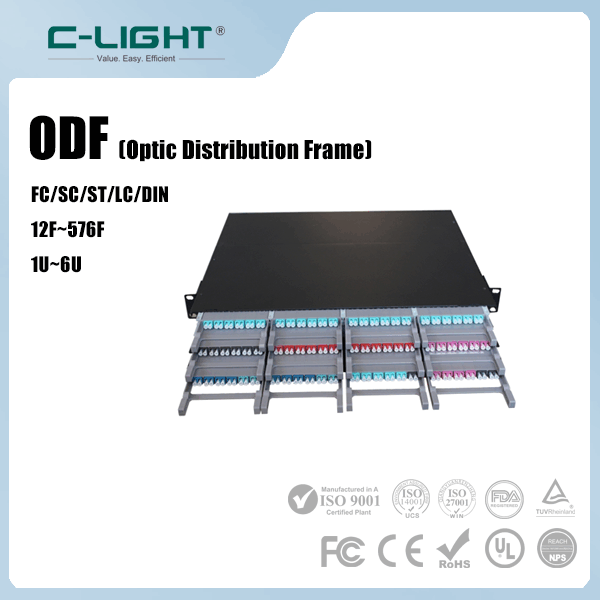
MPO/MTP Fiber Assemblies: High-density fiber connectivity for parallel optical links and structured data center cabling. View MPO/MTP Products.
When evaluating a transceiver, customers should confirm the actual laser technology, optical modulation method, wavelength plan, transmission distance, optical power budget, and host compatibility. The use of silicon photonics or a DFB laser alone does not establish the complete performance specification of a module.
C-LIGHT provides optical transceiver and fiber connectivity solutions for 400G, 800G, and next-generation 1.6T data center applications. Contact our team to discuss product specifications and network requirements.
14. Conclusion
Silicon photonics and DFB lasers play different but complementary roles in modern optical communication systems. Silicon photonics provides an integration platform for optical modulation, waveguiding, multiplexing, and detection. DFB lasers generate the optical signals required for transmission, offering grating-based wavelength selection and stable single-mode operation.
A silicon photonics transceiver can use a DFB laser as an external or integrated light source. This combination allows manufacturers to take advantage of III-V semiconductor laser performance while integrating multiple optical functions on a silicon photonic chip.
For 400G, 800G, and future 1.6T optical transceivers, the most suitable architecture depends on modulation method, optical reach, power consumption, coupling efficiency, thermal design, and manufacturing requirements. Evaluating the complete optical engine rather than treating silicon photonics and DFB as competing technologies leads to a more accurate assessment of transceiver performance.
 >

 >
 >
 >
 >
 >
 >
 >