TEL:+86 132 6656 7067


800G Ethernet provides the bandwidth required by modern AI clusters, hyperscale data centers, and high-performance computing networks. Through port breakout, one 800G switch interface can serve multiple downstream connections instead of operating as a single 800G link.
Two common breakout configurations are 4×200G and 8×100G. Both distribute an aggregate bandwidth of 800Gbps, but they differ in the number of downstream links, bandwidth per connection, electrical lane allocation, and endpoint requirements.
1. Understanding 800G Breakout Architecture
An 800G interface uses multiple high-speed electrical lanes to transfer data between the switch ASIC and the connected cable or optical transceiver. A common architecture uses eight electrical lanes operating at approximately 100Gbps each with PAM4 signaling.
Breakout redistributes these lane resources into multiple downstream interfaces. The two configurations discussed here are:
4×200G: One 800G port is divided into four independent 200G links.
8×100G: One 800G port is divided into eight independent 100G links.
The actual implementation depends on the switch platform, host electrical interface, transceiver or cable design, and downstream connector type.
2. 800G 4×200G Breakout Architecture
The 4×200G configuration divides an 800G port into four independent 200G interfaces. Each downstream connection carries 200Gbps, making this arrangement suitable for newer servers, network adapters, and switches equipped with 200G ports.
Electrical Lane Mapping
In a common implementation, each 200G downstream link uses two 100G-class PAM4 lanes. The eight host-side electrical lanes are therefore organized into four groups, with each group providing one 200G connection.
For optical implementations, the host-side electrical lane structure and optical-side lane structure do not necessarily have to be identical. For example, an 800G optical transceiver may use eight 100G electrical lanes on the host side and four 200G optical lanes on the line side, with a gearbox DSP performing the required conversion.
Typical Applications
Connecting 200G network interface cards in AI and HPC servers.
Building high-bandwidth links between leaf and spine switches.
Connecting 200G-capable switches in high-performance data center fabrics.
Reducing the number of physical downstream connections while maintaining high aggregate throughput.
Advantages and Considerations
Four 200G links provide twice the bandwidth per connection compared with eight 100G links. They also require fewer downstream ports and cable branches, which can simplify physical connectivity when the connected equipment supports 200G.
However, 4×200G requires compatible downstream interfaces. A device with only a 100G port cannot directly use a 200G connection without an appropriate supported network architecture.
3. 800G 8×100G Breakout Architecture
The 8×100G configuration distributes one 800G port across eight independent 100G connections. Each link carries 100Gbps, allowing one high-capacity upstream port to connect to a larger number of downstream devices.
Electrical Lane Mapping
In a common 800G architecture, eight 100G-class PAM4 host lanes are mapped individually to eight 100G downstream links. The cable assembly or optical solution must provide the correct electrical mapping and connector arrangement.
Typical Applications
Connecting multiple 100G network adapters or servers.
Expanding existing 100G data center infrastructure.
Connecting multiple 100G switch ports from a high-capacity upstream interface.
Supporting network upgrades where downstream equipment remains at 100G.
Advantages and Considerations
The main advantage is endpoint density. One 800G port can serve eight 100G connections, making it useful when a network contains many individual 100G devices.
The trade-off is the larger number of downstream ports and cable branches. Cable routing, port availability, and the switch's supported breakout modes should be checked during network planning.
4. Key Technical Differences
| Parameter | 800G 4×200G | 800G 8×100G |
|---|---|---|
| Aggregate bandwidth | 800Gbps | 800Gbps |
| Downstream links | 4 | 8 |
| Bandwidth per link | 200Gbps | 100Gbps |
| Typical lane allocation | Two 100G-class lanes per link | One 100G-class lane per link |
| Endpoint port speed | 200G | 100G |
| Port density | Four downstream connections | Eight downstream connections |
| Typical application | 200G servers and network links | Multiple 100G devices |
| Cabling consideration | Four branches | Eight branches |
5. DAC, AEC, and AOC Connectivity Options
The choice of cable technology depends on transmission distance, signal integrity, cable routing, power consumption, and the supported interfaces on both ends.
800G DAC
Direct Attach Copper uses copper conductors with integrated high-speed connectors. Passive DAC is generally intended for short connections, such as links within the same rack or between adjacent equipment racks.
C-LIGHT's 800G DAC product family includes OSFP112 and QSFP-DD configurations. Listed breakout options include 800G-to-4×200G and selected other configurations. The exact connector combination, cable length, and supported speed depend on the individual model.
800G AEC
Active Electrical Cable integrates signal-conditioning electronics to support electrical transmission under channel conditions where passive copper may not provide sufficient signal margin. AEC can be considered when copper connectivity is preferred but additional signal conditioning is required.
800G AOC
Active Optical Cable uses optical transmission inside an integrated cable assembly. It is suitable for short-reach connections where fiber offers advantages in cable routing, weight, or electromagnetic isolation.
C-LIGHT's 800G AOC product family includes selected OSFP112-to-4×200G OSFP112 configurations, with listed lengths of 1–30m over multimode fiber. Confirm the exact part number and compatibility before selecting a cable.
800G DAC
Medium: Copper
Application: Short-reach equipment connections.
Configurations: Selected 800G breakout options, including 4×200G.
800G AOC
Medium: Multimode optical fiber
Application: Short-reach optical connectivity.
Configurations: Selected 800G-to-200G and other breakout options.
6. Selecting a Breakout Mode for AI and Data Center Networks
The correct configuration depends primarily on the connected devices and the required network topology.
Choose 4×200G When:
Downstream servers or switches have 200G interfaces.
Each connection requires higher bandwidth.
Reducing the number of downstream physical connections is important.
The switch platform supports 4×200G breakout.
Choose 8×100G When:
The connected equipment uses 100G interfaces.
One upstream port needs to serve more individual devices.
The network contains an established 100G infrastructure.
Higher downstream port density is more important than bandwidth per link.
In AI networks, the decision should also account for GPU server architecture, network adapter speed, leaf-spine topology, and the bandwidth requirements of each node. A 200G-based network may benefit from 4×200G, while an environment with many 100G endpoints may be better served by 8×100G.
7. Switch Compatibility and Deployment Checklist
An 800G port does not automatically support every possible breakout configuration. The switch ASIC, SerDes architecture, firmware, and port configuration determine which modes are available.
Switch model: Confirm the specific platform supports 4×200G or 8×100G breakout.
Port type: Verify the upstream 800G interface, such as OSFP or QSFP-DD.
Downstream interface: Confirm the required 200G or 100G connector and module type.
Lane mapping: Check the cable wiring and electrical lane allocation.
FEC settings: Verify the FEC requirements of both ends of the link.
Cable length: Select DAC, AEC, or AOC based on the required reach and signal conditions.
Firmware support: Check supported breakout commands and software versions.
Module compatibility: Verify that the switch recognizes and supports the selected cable or optical module.
Some platforms also restrict breakout modes to specific groups of physical ports. Always check the manufacturer's hardware and software documentation before deployment.
8. C-LIGHT 800G Connectivity Solutions
C-LIGHT provides 800G connectivity products for data center, AI computing, and high-performance networking applications. The portfolio includes 800G DAC, AOC, and optical transceiver solutions for different interface and transmission requirements.
For short-distance copper connections, the 800G DAC series provides direct and breakout cable options. For optical cabling, the 800G AOC series offers selected high-speed breakout assemblies.
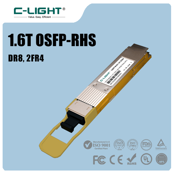
For pluggable optical connectivity, the 800G OSFP optical transceiver family includes SR8, DR8, and 2×FR4 solutions. The appropriate model depends on optical reach, fiber type, connector, and switch compatibility.
When requesting a customized 800G connection, provide the switch model, upstream port type, downstream equipment model, required breakout mode, cable length, and preferred cable technology. These details help determine the appropriate part number and compatibility requirements.
9. Conclusion
800G 4×200G and 8×100G provide two different ways to distribute the same 800Gbps aggregate bandwidth. The 4×200G configuration offers fewer connections with higher bandwidth per link, making it suitable for newer 200G network equipment. The 8×100G configuration provides more downstream connections and supports environments with multiple 100G endpoints.
The right choice depends on endpoint speed, switch breakout support, electrical lane mapping, cable reach, and network topology. Selecting a compatible DAC, AEC, AOC, or optical transceiver ensures that the 800G interface can be integrated into the intended network architecture.
Contact C-LIGHT for 800G DAC, AOC, OSFP, and customized breakout connectivity requirements.
Contact C-LIGHT >

 >
 >
 >
 >
 >
 >
 >