TEL:+86 132 6656 7067


Data center network architecture directly affects application performance, traffic distribution, scalability, and infrastructure costs. As server density and east-west traffic increase, network designs must provide sufficient bandwidth between computing nodes while keeping latency predictable and avoiding unnecessary bottlenecks.
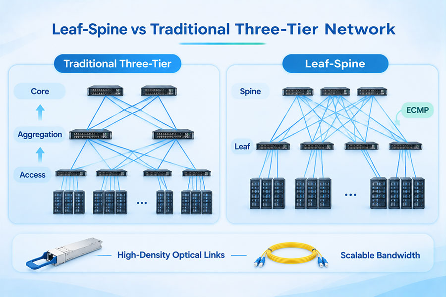
Traditional three-tier architecture has long been used in enterprise and data center networks. It separates access, aggregation, and core functions into hierarchical layers. Leaf-spine architecture takes a flatter approach, connecting server-facing leaf switches to a group of spine switches through a structured fabric. This design is particularly relevant to modern data centers supporting virtualization, distributed storage, cloud platforms, and AI workloads.
1. What Is Traditional Three-Tier Network Architecture?
Traditional three-tier network architecture organizes network devices into three functional layers: access, aggregation, and core. Each layer performs a different role in connecting endpoints, consolidating traffic, and providing connectivity to external networks or other data center environments.
Access Layer
The access layer connects servers, storage systems, workstations, and other endpoint devices to the network. Access switches provide physical connectivity and may handle functions such as VLAN assignment, port security, and basic traffic classification.
Aggregation Layer
The aggregation layer collects traffic from multiple access switches. It commonly provides routing, policy enforcement, redundancy, and traffic management between access networks and the core.
Core Layer
The core layer provides high-speed connectivity between aggregation blocks and connects the data center to other network domains, such as enterprise campuses, WAN infrastructure, and external services. Its primary design objective is to move traffic efficiently across the wider network.
This hierarchical structure allows organizations to separate network functions and apply policies at different layers. It can be practical for enterprise networks with clear departmental boundaries, relatively predictable traffic patterns, and established hierarchical routing requirements.
2. What Is Leaf-Spine Network Architecture?
Leaf-spine architecture is a two-stage network fabric in which every leaf switch connects to every spine switch within the same fabric. Leaf switches provide connectivity to servers and other endpoints, while spine switches interconnect the leaf layer and forward traffic across the data center.
Leaf Layer
Leaf switches connect directly to servers, storage devices, firewalls, load balancers, and other network endpoints. They are often deployed as Top-of-Rack (ToR) or End-of-Row (EoR) switches.
Spine Layer
Spine switches connect the leaf switches and provide high-capacity paths for traffic moving between different racks or leaf domains. In a conventional two-tier leaf-spine fabric, every leaf has an uplink to every spine.
Traffic between endpoints connected to different leaf switches generally follows a predictable two-hop switching path:
The source server sends traffic to its local leaf switch.
The leaf forwards the traffic to an available spine switch.
The spine forwards the traffic to the destination leaf.
The destination leaf delivers the traffic to the target server.
When endpoints are connected to the same leaf switch, their traffic may be forwarded locally without traversing the spine layer.
3. Leaf-Spine vs Traditional Three-Tier: Architecture Differences
Both architectures provide scalable connectivity, but they organize network traffic and expansion differently. Three-tier designs use a hierarchical structure, while leaf-spine designs create a fabric in which leaf switches share connectivity through the spine layer.
| Comparison Factor | Traditional Three-Tier | Leaf-Spine |
|---|---|---|
| Network structure | Access, aggregation, and core layers | Leaf and spine layers |
| Primary design approach | Hierarchical network organization | Fabric-based connectivity |
| Traffic path | May traverse multiple hierarchical layers | Typically leaf to spine to destination leaf |
| East-west traffic | May concentrate traffic at aggregation or core layers | Distributed across multiple spine paths |
| Latency characteristics | Depends on the number of hops and network design | More predictable between different leaf switches |
| Scalability | Expanded through hierarchical blocks and uplinks | Expanded by adding leaf switches and, when required, spine capacity |
| Load balancing | Depends on topology and supported routing mechanisms | Commonly uses ECMP across equal-cost paths |
| Oversubscription | Can occur at access uplinks, aggregation, or core links | Can be engineered through leaf uplink capacity and spine bandwidth |
| Typical applications | Enterprise networks and traditional data centers | Cloud data centers, virtualization, AI and HPC environments |
Neither architecture automatically guarantees better performance. Actual results depend on switch capacity, uplink speed, traffic distribution, routing configuration, oversubscription, and the quality of the physical connectivity.
4. Network Latency and Traffic Flow
Latency is an important consideration when designing networks for distributed applications, storage systems, and AI workloads. Each additional switching stage can introduce forwarding delay, queuing, and potential congestion.
In a traditional three-tier network, traffic between endpoints in different access blocks may pass through aggregation and core devices, depending on the topology. Traffic paths can therefore vary according to endpoint location and routing design.
In a conventional two-tier leaf-spine network, traffic between different leaf switches generally passes through one spine switch. This creates a consistent switching-stage count for inter-leaf communication.
However, hop count alone does not determine end-to-end latency. Other important factors include:
Switch forwarding latency and packet-processing architecture.
Port speed and interface utilization.
Queue depth and congestion management.
Packet size and traffic burst characteristics.
Routing decisions and load-balancing behavior.
Fiber transmission distance and optical interface performance.
A well-engineered three-tier network can provide low latency for its intended traffic patterns. Similarly, a leaf-spine network can experience congestion if uplink bandwidth is insufficient or traffic is unevenly distributed.
5. East-West Traffic and Network Bandwidth
East-west traffic refers to communication between servers, storage systems, and application components within a data center. North-south traffic generally refers to communication between the data center and external networks or users.
Traditional hierarchical networks were often designed around client-to-server communication and north-south traffic patterns. As virtualization, distributed databases, container platforms, and AI computing have expanded, east-west traffic has become increasingly significant.
Leaf-spine architecture is well suited to these traffic patterns because multiple spine switches provide paths between leaf switches. With appropriate routing and capacity planning, traffic can be distributed across multiple equal-cost paths.
For example, in an AI training cluster, servers and accelerators may exchange large volumes of data during distributed computation. The network must provide sufficient bandwidth between racks while controlling congestion and maintaining predictable communication paths.
Three-tier networks can also support east-west traffic, but the aggregation and core layers must be sized appropriately. If these layers become bandwidth bottlenecks, additional capacity or topology changes may be necessary.
6. ECMP and Load Balancing in Leaf-Spine Networks
Equal-Cost Multipath (ECMP) is a common routing mechanism in leaf-spine networks. It allows traffic to use multiple paths with equal routing cost between network destinations.
Because each leaf switch connects to multiple spine switches, the fabric can provide several available paths for traffic moving between leaf domains. ECMP distributes traffic across these paths according to the routing implementation and flow-selection mechanism.
Common benefits include:
Better utilization of available uplink and spine bandwidth.
Multiple paths between leaf switches.
Improved resilience when a supported path becomes unavailable.
Reduced dependence on a single inter-switch link.
More flexible capacity expansion.
ECMP does not necessarily distribute every individual packet evenly across all paths. Many implementations use flow-based hashing to maintain packet ordering. Uneven flow sizes can therefore create traffic imbalance, even when multiple paths are available.
Network engineers should consider ECMP hashing, link utilization, routing convergence, and failure behavior when validating a leaf-spine design.
7. Scalability and Network Expansion
Scalability is one of the main reasons data center operators adopt leaf-spine architecture. As the number of servers and racks increases, additional leaf switches can be connected to the existing spine layer, provided that sufficient ports and bandwidth are available.
Expanding a Leaf-Spine Fabric
When more server-facing ports are needed, additional leaf switches can be introduced. When the existing spine layer reaches its port or capacity limits, additional spine switches or a redesigned fabric may be required.
For larger environments, operators may use multi-plane fabrics, multiple network pods, or additional stages of network interconnection. These designs extend the basic leaf-spine concept while managing port density and overall fabric capacity.
Expanding a Three-Tier Network
Traditional three-tier networks can also scale by adding access switches, aggregation blocks, and core capacity. However, expansion may require careful planning around hierarchical uplinks, routing boundaries, redundancy, and oversubscription.
The best approach depends on the number of endpoints, traffic patterns, equipment capabilities, and the organization's existing network architecture.
8. Oversubscription and Bandwidth Planning
Oversubscription occurs when the total potential bandwidth from downstream interfaces exceeds the available upstream capacity. It is a common design consideration in both network architectures.
For example, a leaf switch may provide 48 server-facing ports operating at 25Gbps each, resulting in 1.2Tbps of nominal server-facing bandwidth. If its uplinks provide a combined 600Gbps, the nominal downlink-to-uplink bandwidth ratio is 2:1.
This does not mean that the switch will always experience congestion. The impact depends on actual traffic demand, flow distribution, and how much bandwidth endpoints use simultaneously.
In leaf-spine networks, oversubscription is often evaluated at the leaf layer by comparing server-facing capacity with the total spine-facing uplink capacity.
In three-tier networks, oversubscription can occur at several points, including access-to-aggregation links and aggregation-to-core links.
| Design Consideration | Leaf-Spine | Traditional Three-Tier |
|---|---|---|
| Access bandwidth | Server-facing leaf port capacity | Server-facing access switch capacity |
| Uplink capacity | Leaf-to-spine links | Access-to-aggregation links |
| Core capacity | Spine-layer switching capacity | Core-layer switching capacity |
| Oversubscription analysis | Often evaluated at each leaf and across the fabric | Evaluated at each hierarchical layer |
| Expansion planning | Additional leaf or spine capacity | Additional access, aggregation, or core capacity |
Bandwidth planning should use realistic traffic profiles rather than assuming that every endpoint will continuously transmit at its maximum port rate. AI training, storage replication, backup traffic, and general application traffic can have very different utilization patterns.
9. Reliability, Redundancy, and Network Resilience
Network availability depends on how the architecture handles equipment, link, and power failures. Both leaf-spine and three-tier designs can provide redundancy, but the implementation differs.
In a leaf-spine fabric, each leaf typically connects to multiple spine switches. If a spine switch or one of its links becomes unavailable, routing can use remaining available paths, provided the fabric has sufficient redundancy and capacity.
Traditional three-tier networks commonly use redundant access uplinks, aggregation switches, and core devices. Redundant paths and gateway mechanisms can help maintain connectivity when individual components fail.
Reliability planning should address:
Redundant switch devices and power supplies.
Multiple physical uplinks and diverse cable routes.
Routing convergence and failure detection.
Available capacity after a device or link failure.
Configuration consistency across redundant paths.
Monitoring, alerting, and recovery procedures.
Redundancy alone does not guarantee uninterrupted service. A network must also retain enough bandwidth after a failure, and its routing behavior must be validated under realistic fault conditions.
10. Optical Connectivity Requirements in Leaf-Spine Networks
Leaf-spine architecture increases the importance of high-density inter-switch connectivity. Every leaf switch requires connections to the spine layer, and the number of optical links grows with the number of switches, port speeds, and fabric design.
Optical transceivers and fiber assemblies must be selected according to link distance, port speed, fiber type, connector interface, and host compatibility.
Common connectivity options include:
10G and 25G: Used in server access and smaller network deployments.
100G: Commonly used for leaf-to-spine uplinks and higher-speed server connections.
400G: Supports high-capacity spine links and modern data center switching.
800G: Used in high-bandwidth AI and hyperscale network fabrics.
1.6T: Emerging for next-generation data center and AI infrastructure.
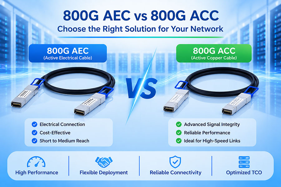
For short-reach connections, DAC and AEC assemblies may be suitable depending on distance, port density, and power requirements. For longer links or greater flexibility, optical transceivers and fiber cabling are commonly used.
Fiber selection also matters. Single-mode and multimode links have different reach, wavelength, and optical interface requirements. MPO/MTP assemblies may be used for parallel optical interfaces, while duplex LC connections are common for many single-mode and duplex applications.
11. Which Architecture Is Better for AI Data Centers?
AI data centers place demanding requirements on network bandwidth, latency, congestion control, and scalability. Distributed training workloads can generate substantial east-west traffic as GPUs and other accelerators exchange data across multiple servers and racks.
Leaf-spine architecture is widely suited to these environments because it provides structured connectivity between server-facing switches and multiple spine paths. It can be engineered to support high-capacity fabrics using Ethernet or InfiniBand switching technologies.
However, the architecture alone does not determine AI network performance. Important design factors include:
GPU and accelerator communication patterns.
Network interface speed and server connectivity.
Switch radix, port count, and fabric bandwidth.
Oversubscription and congestion management.
RoCEv2 or InfiniBand configuration requirements.
Optical transceiver reach, power consumption, and thermal performance.
For smaller enterprise environments, a three-tier architecture may remain appropriate. For large-scale AI clusters and cloud data centers, leaf-spine or more advanced fabric designs are often better aligned with high-volume east-west traffic.
12. When Should You Choose Leaf-Spine or Three-Tier Architecture?
The right network topology depends on application requirements, infrastructure scale, existing equipment, operational expertise, and expansion plans.
| Requirement | Suitable Architecture | Reason |
|---|---|---|
| Large-scale east-west traffic | Leaf-spine | Provides multiple paths between leaf switches |
| AI and HPC clusters | Leaf-spine or advanced fabric | Supports high-bandwidth inter-rack communication |
| Traditional enterprise hierarchy | Three-tier | Provides clear functional separation between network layers |
| Existing access-aggregation-core infrastructure | Three-tier | Can preserve existing investments and operational processes |
| Predictable inter-rack switching paths | Leaf-spine | Uses a consistent two-stage inter-leaf path in a conventional fabric |
| Gradual hierarchical expansion | Three-tier | Allows capacity to be added at individual network layers |
| High-density data center switching | Leaf-spine | Supports structured scaling of leaf ports and spine capacity |
Some organizations also use hybrid designs. For example, a data center may deploy leaf-spine fabrics internally while retaining a core layer for WAN connectivity, campus integration, security services, or inter-data-center communication.
13. C-LIGHT Optical Connectivity for Modern Data Center Fabrics
As data center networks evolve toward higher port speeds and greater switching density, optical connectivity becomes a key part of the physical infrastructure. Leaf-to-spine links must meet the required bandwidth, reach, optical power budget, and host compatibility specifications.
C-LIGHT provides optical transceivers and connectivity products for data center, cloud computing, and AI infrastructure applications. Relevant product categories include:
400G OSFP Optical Transceivers: Designed for high-speed switching and interconnect applications, with options for different optical reaches and fiber configurations. View 400G OSFP Products.
800G OSFP Optical Transceivers: Supports high-bandwidth data center fabrics and AI infrastructure. Product categories include SR8, DR8, and 2×FR4 configurations. View 800G OSFP Products.
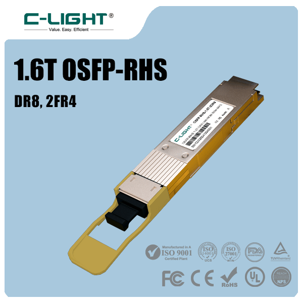
1.6T OSFP-RHS Optical Transceivers: Designed for emerging high-density switching platforms and next-generation AI connectivity. View 1.6T OSFP-RHS Products.
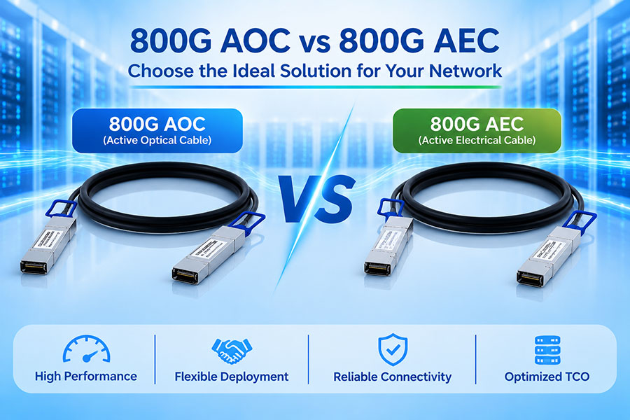
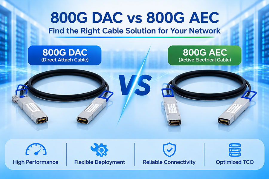
400G and 800G DAC/AEC Solutions: Short-reach electrical connectivity options for server, switch, and accelerator connections. View DAC and AOC Products.
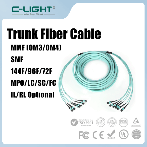
MPO/MTP Fiber Connectivity: Multi-fiber cabling solutions for parallel optical links and high-density data center distribution. View MPO/MTP Products.
Optical Transceiver Portfolio: Covers multiple data rates and application categories for enterprise, telecom, and data center networks. Browse Optical Transceiver Products.
When selecting optical modules for a leaf-spine deployment, network designers should verify switch compatibility, port speed, optical reach, fiber type, connector configuration, power consumption, and cooling requirements. These parameters help ensure that the optical layer can support the planned fabric capacity.
C-LIGHT provides optical transceiver and fiber connectivity solutions for 100G, 400G, 800G, and next-generation 1.6T applications. Contact our team to discuss optical module specifications and connectivity requirements for your network architecture.
14. Conclusion
Traditional three-tier and leaf-spine architectures serve different network design requirements. Three-tier networks provide a hierarchical structure with access, aggregation, and core layers, making them suitable for many enterprise environments and established data center infrastructures.
Leaf-spine architecture offers a flatter fabric with predictable inter-leaf switching paths and multiple equal-cost routes. It is particularly useful for modern data centers where east-west traffic, high port density, and scalable bandwidth are major priorities.
The best design depends on traffic patterns, application requirements, network scale, redundancy targets, and operational considerations. As data center infrastructure moves toward 400G, 800G, and 1.6T connectivity, careful planning of switching capacity, optical links, and fiber infrastructure becomes increasingly important for maintaining efficient and reliable network performance.
 >

 >
 >
 >
 >
 >
 >
 >