TEL:+86 132 6656 7067


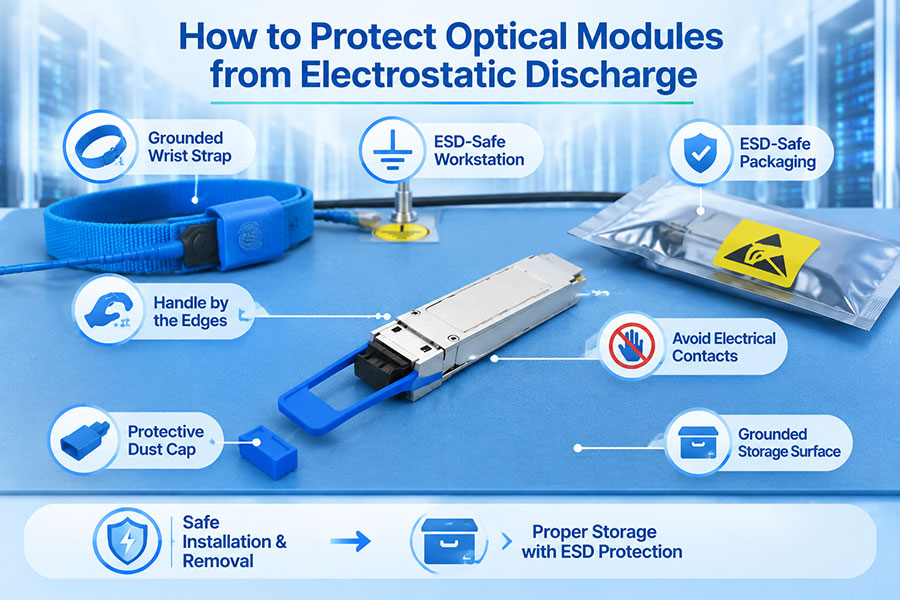
Optical transceivers combine sensitive semiconductor devices, high-speed electronic circuits, laser components, and photodetectors in compact modules. Although these components are designed for demanding network environments, they can be vulnerable to electrostatic discharge (ESD) during manufacturing, transportation, installation, and maintenance.
An electrostatic discharge may occur when a charged person, tool, or surface comes into contact with an electronic component. Some ESD events cause immediate failure, while others create latent damage that affects long-term reliability. As networks adopt 400G, 800G, and 1.6T optical interfaces, consistent ESD protection is an essential part of optical module handling and quality control.
1. What Is Electrostatic Discharge (ESD)?
Electrostatic discharge is the sudden transfer of electrical charge between objects with different electrical potentials. Static electricity can accumulate on people, clothing, packaging materials, work surfaces, and equipment through contact, separation, or friction.
When a charged object contacts an electronic component or conductive interface, the accumulated charge may discharge through a sensitive circuit. The resulting electrical stress can damage semiconductor structures or affect component performance.
ESD is not always visible or noticeable. A discharge that is too small to be felt by a person may still exceed the tolerance of a sensitive electronic device.
2. Why Are Optical Modules Sensitive to ESD?
Optical transceivers contain several electronic and optoelectronic components that require controlled handling. These include laser drivers, receiver amplifiers, control circuits, monitoring components, and high-speed electrical interfaces.
Potentially sensitive areas include:
Laser driver circuits: Electronic circuits that control the optical transmitter.
Receiver circuitry: Photodetector-related circuits and amplification stages that process incoming optical signals.
Control and monitoring ICs: Components responsible for module management, diagnostics, and communication with the host device.
High-speed electrical interfaces: Contacts and circuits connecting the module to the switch, router, or server.
Power management circuits: Components that regulate electrical power within the module.
The exact ESD sensitivity depends on the internal design and protection measures of each product. A module's mechanical housing does not necessarily provide complete protection for its internal electronic components.
3. How ESD Can Affect Optical Transceiver Performance
ESD damage can range from immediate component failure to subtle degradation that is difficult to identify during initial testing.
| Potential ESD Effect | Possible Symptom | Network Impact |
|---|---|---|
| Transmitter circuit damage | Abnormal transmit optical power or failure to transmit | Optical link instability or link failure |
| Receiver circuit degradation | Abnormal receiver behavior or reduced signal margin | Unreliable signal reception |
| Control IC damage | Missing or incorrect module information | Module identification or management problems |
| Electrical interface damage | Communication errors between the module and host | Port recognition or interface problems |
| Latent component damage | Intermittent or premature failure | Reduced long-term reliability |
Not every optical power or link problem is caused by ESD. Fiber contamination, incorrect compatibility settings, excessive optical loss, temperature, and other electrical faults can produce similar symptoms. Proper testing is necessary to identify the actual cause.
4. Use a Properly Grounded ESD-Protected Workstation
A controlled ESD workstation is one of the most important protections when handling exposed optical modules. Its purpose is to reduce potential differences between the technician, work surface, tools, and electronic components.
ESD Workstation Components
ESD work surface: A suitable dissipative mat connected to the designated grounding system.
Wrist strap: A properly fitted and tested wrist strap connected through an approved grounding point.
ESD grounding connection: A controlled grounding system designed for the work area.
ESD-safe storage trays: Containers designed to hold sensitive electronic modules safely.
ESD monitoring equipment: Devices used to verify the condition of wrist straps and grounding connections.
All components should be selected and maintained according to the facility's ESD control program. A properly configured workstation helps keep handled items at a controlled electrical potential and reduces the risk of damaging discharge events.
5. Wear an ESD Wrist Strap When Handling Optical Modules
A wrist strap helps prevent charge accumulation on the technician's body from being transferred to a sensitive electronic component. It is a standard control in many electronics manufacturing, testing, and repair environments.
Recommended practices include:
Wear an approved wrist strap when handling exposed modules at an ESD-controlled workstation.
Ensure the strap makes proper contact with the skin.
Connect it to the designated ESD grounding point.
Test the wrist strap according to the facility's procedures and required frequency.
Replace damaged straps or connection cables.
Continue following ESD procedures when transferring modules between workstations.
A wrist strap is one element of an ESD control system, not a substitute for suitable packaging, grounding, and work-area controls.
6. Use Antistatic Packaging for Transportation and Storage
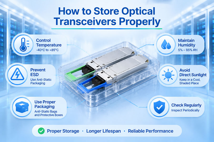
Optical transceivers should remain in suitable ESD-protective packaging whenever they are not being handled. Packaging helps reduce exposure to electrostatic fields, direct discharge, dust, and mechanical damage.
Common packaging options include:
| Packaging Type | Primary Function | Typical Use |
|---|---|---|
| Static-shielding bag | Provides protection against external electrostatic fields and discharge when properly specified | Individual module packaging and transportation |
| Conductive container | Provides a conductive enclosure for controlled component storage | ESD-controlled storage and handling |
| ESD-safe tray | Separates modules and reduces handling damage | Manufacturing, testing, and inventory storage |
| Protective module case | Provides mechanical protection and helps prevent accidental contact | Field service and equipment transportation |
Ordinary plastic bags and foam materials should not be assumed to provide ESD protection. Use packaging with appropriate ESD performance and follow the supplier's handling instructions.
7. Handle Optical Modules by Their Housing
Correct handling reduces the chance of transferring static charge, contamination, or mechanical stress to sensitive module interfaces. Technicians should hold transceivers by their designated housing surfaces rather than touching electrical contacts or optical interfaces.
Follow these handling practices:
Hold the module by its housing or designated handling surfaces.
Avoid touching electrical contacts and exposed circuit areas.
Do not touch optical receptacles or internal alignment surfaces.
Avoid placing modules on ordinary plastic bags, clothing, or other uncontrolled surfaces.
Do not allow loose modules to contact one another during handling.
Return unused modules to approved ESD-protective packaging promptly.
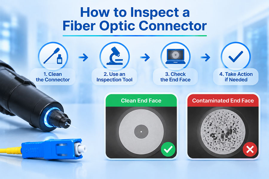
These practices also help prevent contamination and mechanical damage, making them useful for both optical module reliability and connector cleanliness.
8. Control the ESD Environment
ESD risk is influenced by the surrounding environment. Low humidity can increase static charge accumulation, while unsuitable flooring, furniture, clothing, and packaging can create additional sources of charge.
A complete ESD control program should address more than the module itself.
Environmental Control Measures
Use ESD-safe flooring or grounding systems where required by the facility design.
Use approved ESD garments and footwear in designated controlled areas.
Keep work surfaces and storage areas free from unnecessary insulating materials.
Monitor environmental conditions according to the site's ESD control plan.
Use ionization equipment where appropriate for insulating materials that cannot be eliminated.
Inspect and maintain ESD workstations, grounding points, and monitoring equipment.
Humidity control may help reduce static generation, but it should not replace grounding, approved packaging, or other required ESD controls. Environmental targets should follow the facility's ESD program and applicable standards.
9. Follow ESD Procedures During Installation and Removal
Optical modules are particularly exposed to handling risks during installation, replacement, and troubleshooting. A technician may remove a module from a switch, inspect its label, test it, and move it between several locations. Each handling step should preserve ESD protection.
A controlled installation process includes:
Prepare an ESD-protected work area before removing the module from its packaging.
Verify the grounding and wrist-strap arrangements according to the site's procedures.
Remove the module from its ESD bag only when ready for installation.
Hold the module by its housing and avoid contact with electrical interfaces.
Install it using the manufacturer's recommended insertion and removal procedure.
Place removed or unused modules into suitable ESD-protective packaging.
Record any suspected handling incident or abnormal module behavior.
When removing modules from operating network equipment, follow the equipment manufacturer's procedures and observe applicable optical laser-safety requirements.
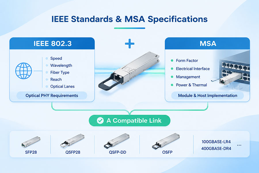
10. ESD Protection for Different Optical Transceiver Form Factors
ESD protection principles apply to all optical transceiver families, regardless of data rate or physical size. However, module dimensions, electrical interfaces, and handling arrangements differ across form factors.
| Transceiver Family | Examples | Handling Considerations |
|---|---|---|
| SFP Family | SFP, SFP+, SFP28, SFP56, SFP112 | Protect electrical contacts, optical receptacles, and latch mechanisms |
| QSFP Family | QSFP+, QSFP28, QSFP56, QSFP112 | Use suitable ESD trays and avoid pressure on the housing and pull tab |
| QSFP-DD | 400G and other supported high-speed modules | Maintain ESD protection across handling, testing, and storage |
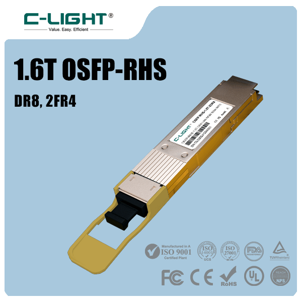
| OSFP | 800G and 1.6T modules | Use packaging designed for the module dimensions and interface |
| Coherent pluggables | Coherent optical transceiver modules | Follow model-specific handling and storage instructions |
Higher data rates do not automatically mean that a module has a lower ESD tolerance. The ESD sensitivity of a product depends on its internal electronic design and protection measures, not simply its transmission speed.
11. ESD Protection During Manufacturing and Quality Testing
Optical transceiver manufacturers and testing facilities should maintain ESD controls throughout assembly, inspection, programming, and performance testing. A module may pass optical testing but still be exposed to unnecessary ESD risk during subsequent handling if the work area is not controlled.
Typical manufacturing and quality-control measures include:
ESD-protected assembly and testing workstations.
Grounded operator equipment and approved handling tools.
ESD-safe trays for work-in-process modules.
Protective packaging during transfers between production stages.
Periodic inspection and testing of ESD control equipment.
Operator training and documented handling procedures.
Traceability for products involved in suspected ESD incidents.
ESD controls should be integrated into the overall quality-management process rather than treated as a separate final inspection activity.
12. Common ESD Protection Mistakes to Avoid
Even experienced technicians can introduce ESD risks through inconsistent handling. The following mistakes should be avoided:
Handling modules without grounding: Exposed modules should be handled in accordance with an established ESD control procedure.
Using ordinary plastic packaging: General-purpose bags may generate or retain static charge.
Touching electrical contacts: Direct contact increases the risk of contamination and unwanted electrical discharge.
Leaving modules exposed: Unprotected components are more vulnerable during storage and transportation.
Ignoring wrist-strap testing: A damaged or incorrectly connected wrist strap may not provide the intended protection.
Relying only on humidity: Humidity management does not replace a complete ESD control program.
Mixing ESD-safe and uncontrolled materials: Unsuitable surfaces and packaging can undermine workstation protection.
Assuming a working module is undamaged: Latent ESD damage may not cause an immediate failure.
13. ESD Protection Checklist for Optical Module Handling
A documented checklist helps standardize ESD protection across manufacturing, warehouse storage, field installation, and network maintenance.
| Stage | Recommended Control | Purpose |
|---|---|---|
| Before handling | Prepare an ESD-protected workstation | Reduce uncontrolled charge transfer |
| Operator preparation | Use and verify approved grounding equipment | Maintain controlled electrical potential |
| Module removal | Open approved ESD packaging at the workstation | Protect the module during unpacking |
| Handling | Hold the module by its housing | Avoid direct contact with sensitive interfaces |
| Testing | Use ESD-controlled equipment and fixtures | Protect the module during diagnostics |
| Storage | Return unused modules to approved packaging | Maintain protection between operations |
| Transportation | Use suitable ESD-protective containers | Reduce exposure during movement |
14. C-LIGHT Optical Transceiver Solutions
As optical networks move toward higher bandwidth and greater port density, product quality and careful handling become increasingly important. C-LIGHT provides optical connectivity products for data center, telecom, and high-performance computing applications.
Relevant product categories include:
100G optical transceivers: QSFP28 modules for data center and telecom connectivity.
400G optical transceivers: QSFP-DD, OSFP, and QSFP112 solutions for high-bandwidth network architectures.
800G optical transceivers: High-speed connectivity for AI clusters and next-generation data centers.
1.6T optical transceivers: Emerging high-capacity interfaces for future network infrastructure.
DAC and AEC cables: Short-reach electrical connectivity for compatible switch and server platforms.
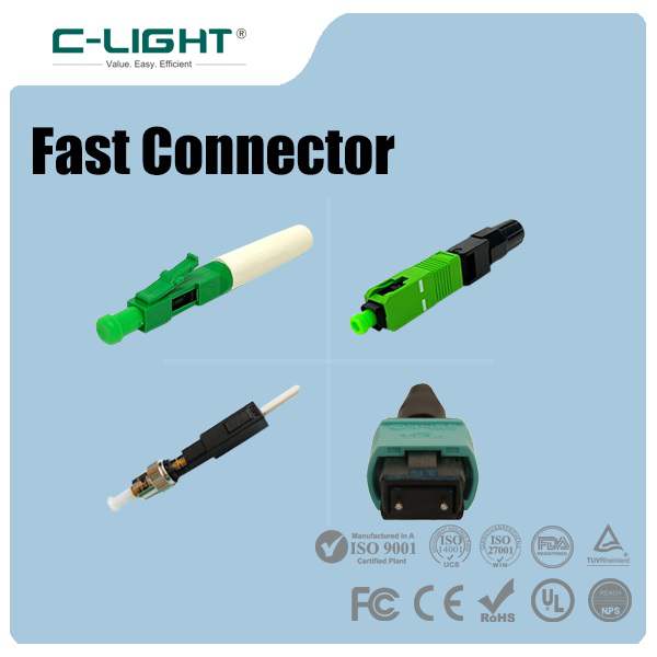
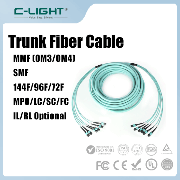
MPO/MTP fiber solutions: High-density optical connectivity for parallel-fiber applications.
Correct module selection, compatibility verification, and appropriate ESD handling all contribute to reliable optical network deployment. For product specifications, compatibility requirements, or customized optical connectivity solutions, Contact C-LIGHT.
15. Conclusion
Protecting optical modules from electrostatic discharge requires consistent controls throughout manufacturing, storage, transportation, installation, and maintenance. Grounded ESD workstations, properly tested wrist straps, approved antistatic packaging, and correct handling procedures are the foundation of effective protection.
These practices help reduce both immediate and latent ESD damage across SFP, QSFP, QSFP-DD, OSFP, and other optical module families. As 400G, 800G, and 1.6T connectivity becomes more widely deployed, a disciplined ESD control process remains an important part of optical equipment reliability and quality assurance.
 >

 >
 >
 >
 >
 >
 >
 >