TEL:+86 132 6656 7067


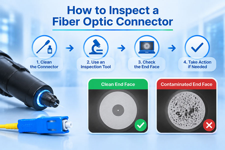
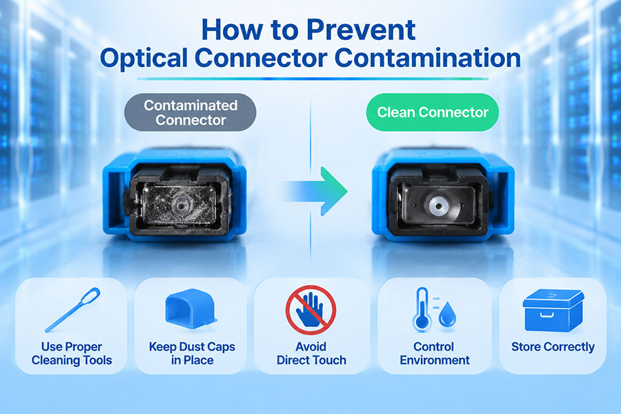
Fiber optic connector performance depends on more than the quality of the optical module or cable. The condition of the connector end face directly affects how light enters and exits the fiber. Dust, oil, scratches, and other contaminants can increase insertion loss, cause unstable readings, and contribute to link failures, particularly in high-density 100G, 400G, 800G, and 1.6T data center networks.
Connector inspection is therefore an essential part of fiber installation, maintenance, troubleshooting, and acceptance testing. A repeatable inspection process helps technicians identify contamination and physical defects before connecting optical interfaces or placing links into service.
1. Why Fiber Optic Connector Inspection Matters
A fiber optic connector aligns two fiber end faces so that optical signals can pass between them. Even small particles or surface defects near the fiber core can interfere with this optical coupling.
Connector contamination can lead to several performance problems:
Higher insertion loss: Contamination or poor physical contact can reduce the optical power received by the connected device.
Increased return loss: Certain end-face defects and connection conditions can increase reflected optical power.
Intermittent connectivity: Contamination or unstable physical contact may cause fluctuating optical readings or link interruptions.
Permanent end-face damage: Connecting contaminated surfaces can transfer debris or cause scratches that cannot be removed through routine cleaning.
Unnecessary troubleshooting: A dirty connector can be mistaken for a defective transceiver, cable, or network port.
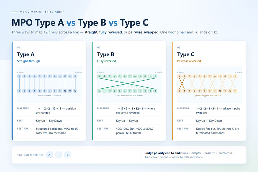
These risks become more significant in high-density optical systems. MPO/MTP trunk cables, parallel-optics transceivers, and high-speed links often contain multiple optical channels within a compact connector interface. A single connector inspection can therefore help prevent problems across several lanes.
2. Tools Required for Fiber Connector Inspection
Visual inspection requires equipment designed specifically for fiber optic end faces. Looking at a connector with the naked eye is not sufficient to determine whether its optical surface is clean and free from defects.
| Inspection Tool | Primary Function | Typical Application |
|---|---|---|
| Video fiber inspection microscope | Displays a magnified image of the connector end face on a screen | Routine inspection of LC, SC, FC, and other connector types |
| Inspection probe | Provides access to connector interfaces inside adapters and equipment ports | Patch panels, transceiver receptacles, and installed connections |
| Fiber cleaning pen | Uses a controlled cleaning mechanism to remove contamination | Compatible connector end faces, depending on the pen design |
| Lint-free cleaning wipes | Provides a clean surface for controlled end-face cleaning | Connector ferrules and approved cleaning procedures |
| Fiber cleaning solvent | Helps dissolve oils and other residues when used with approved materials | Wet cleaning followed by a dry cleaning step |
| Connector inspection software | Supports image capture, defect identification, and pass/fail assessment | Quality control and documented acceptance testing |
For routine field work, a video inspection microscope with interchangeable tips is particularly useful. It allows technicians to inspect both accessible connector ends and recessed interfaces without directly viewing the optical fiber.
3. Understanding the Fiber Connector End Face
A fiber connector end face is not a single uniform surface. Inspection systems evaluate different regions around the fiber core because contamination and damage in each region can have different effects on optical performance.
For common single-fiber connectors, the inspection image generally includes the following areas:
Core: The central region that carries the optical signal. Contamination or damage here is particularly important.
Cladding: The glass region surrounding the core. Defects in this area may affect the fiber interface and its acceptance assessment.
Adhesive region: The area surrounding the glass fiber, where adhesive or residue may be visible.
Contact region: The surrounding ferrule surface that contributes to physical contact and connector alignment.
Automated inspection systems commonly divide the end face into concentric zones and evaluate defects according to their size, location, and applicable acceptance criteria. The precise zone definitions and limits depend on the inspection standard, fiber type, and connector configuration.
4. Step-by-Step Fiber Optic Connector Inspection
A consistent inspection sequence helps reduce contamination and prevents technicians from overlooking defects. The recommended workflow is to inspect, clean when necessary, and inspect again before connection.
Step 1: Identify the Connector Type
Determine whether the connector is LC, SC, FC, ST, MPO/MTP, or another type. Check whether it uses a UPC or APC polish where applicable. Select a compatible inspection probe and adapter before examining the end face.
Step 2: Make the Interface Safe to Inspect
Disconnect the connector from the optical interface when the inspection procedure requires it. Follow the equipment manufacturer's laser-safety instructions and confirm that the inspection method is suitable for the optical system.
Step 3: Select the Correct Inspection Probe
Choose a probe tip that matches the connector geometry. Use a suitable adapter for external connector inspection and a dedicated inspection probe for recessed ports. An incorrect tip can prevent proper alignment and produce an incomplete image.
Step 4: Inspect the End Face
Position the connector carefully and adjust focus until the fiber end face is clearly visible. Examine the core, cladding, adhesive region, and ferrule surface. Look for particles, oil, residue, scratches, pits, and other visible defects.
Step 5: Evaluate the Inspection Result
Use the inspection system's image analysis and the applicable acceptance criteria to determine whether the connector passes. Do not judge connector quality solely by whether the end face looks clean at low magnification.
Step 6: Clean if Necessary
If contamination is detected, use a compatible cleaning method. Avoid touching the fiber end face with fingers or ordinary cloth. Cleaning materials should be designed for optical connectors and kept free from dust and residue.
Step 7: Inspect Again Before Connection
Repeat the inspection after cleaning. If contamination remains, repeat the approved cleaning process. If scratches, chips, or other physical damage remain, do not assume that additional cleaning will restore the connector. Replace or refer the connector for appropriate evaluation.
5. Common Fiber Connector Contamination and Defects
Different types of contamination and physical damage can appear similar in an inspection image. Identifying the type of defect helps determine whether cleaning is likely to resolve the problem or whether the connector requires replacement.
| Defect Type | Typical Appearance | Recommended Response |
|---|---|---|
| Dust particles | Small isolated spots or irregular particles | Clean using an approved connector cleaning method and reinspect |
| Oil or fingerprints | Smears, films, or irregular residue | Use a compatible wet-and-dry cleaning procedure |
| Cleaning residue | Streaks or films remaining after cleaning | Repeat with clean, approved materials and inspect again |
| Scratches | Linear marks across the end face | Evaluate against the applicable acceptance criteria; replace if unacceptable |
| Pits or chips | Small cavities or missing material | Assess the defect location and size; replace if outside acceptance limits |
| Adhesive contamination | Irregular material around the fiber or ferrule | Use an approved evaluation process; do not scrape the optical surface |
Cleaning can remove foreign material, but it cannot repair physical damage to the glass or ferrule. This distinction is important when troubleshooting a connector that continues to fail inspection after repeated cleaning.
6. Fiber Optic Connector Cleaning Methods
Connector cleaning methods generally fall into dry cleaning, wet cleaning, and combined wet-and-dry cleaning. The correct choice depends on the type of contamination, connector design, and cleaning equipment.
Dry Cleaning
Dry cleaning tools include connector cleaning pens, cassette cleaners, and approved lint-free cleaning materials. They are commonly used to remove loose dust and particles from accessible connector end faces.
Wet Cleaning
Wet cleaning uses an approved optical cleaning solvent and compatible lint-free materials to help remove oils and stubborn residue. The solvent must be suitable for the connector and cleaning system. Excess liquid or incompatible chemicals can leave residue or damage materials.
Wet-and-Dry Cleaning
For contamination that does not respond to dry cleaning, a controlled wet-and-dry process may be appropriate. The wet step loosens contamination, while the dry step removes remaining solvent and residue.
7. How to Inspect LC, SC, and MPO/MTP Connectors
Different connector formats require different inspection approaches. Connector size, ferrule design, fiber count, and physical access all influence the inspection procedure.
LC Connectors
LC connectors use a compact ferrule and are widely deployed in high-density data center patch panels and optical transceivers. Their small form factor makes a compatible inspection probe important. Both UPC and APC versions should be identified correctly before inspection.
SC Connectors
SC connectors use a larger push-pull housing and are common in telecom, access networks, and fiber distribution systems. Inspection focuses on the end face and the condition of the ferrule, with the probe selected for the connector's polish and geometry.
MPO/MTP Connectors
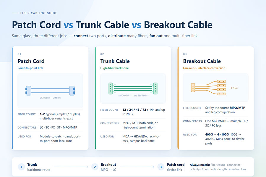
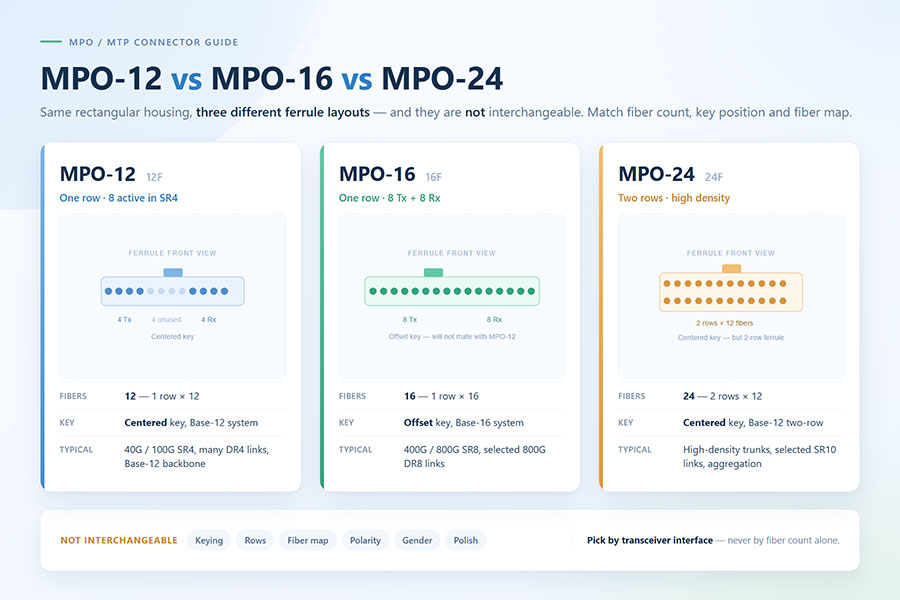
MPO/MTP connectors contain multiple fibers arranged in a single ferrule. Their inspection requires a multi-fiber inspection system capable of displaying and evaluating the individual fiber positions.
Technicians should check for contamination across the entire fiber array, not just the center positions. They should also examine the guide-pin region and ferrule surface where relevant. A connector may have several clean fibers while one or more positions remain contaminated or damaged.
| Connector Type | Inspection Requirement | Common Deployment |
|---|---|---|
| LC | Single-fiber inspection with a compatible small-form-factor probe | 10G, 25G, 100G, and duplex optical links |
| SC | Single-fiber inspection with an SC-compatible probe | Telecom, FTTH, and optical distribution systems |
| FC | Inspection using a probe compatible with the threaded connector design | Test equipment and specialized optical systems |
| MPO/MTP | Multi-fiber inspection covering every fiber position | 40G, 100G, 400G, 800G, and high-density data center cabling |
8. Understanding IEC 61300-3-35 Inspection Criteria
IEC 61300-3-35 is an important reference for visual inspection and acceptance assessment of fiber optic connector end faces. It provides a framework for evaluating contamination and physical defects in defined regions of the connector end face.
Inspection systems designed around this standard can analyze factors such as:
Contamination particles and their distribution.
Scratches and surface defects.
Defect size and location within defined inspection zones.
Acceptance results based on the applicable connector and fiber requirements.
Acceptance limits are not universal across every connector and fiber configuration. The applicable standard edition, connector type, fiber type, and project requirements must be considered when setting pass/fail thresholds.
Automated inspection software can improve consistency by capturing images and applying defined evaluation rules. However, technicians should understand the inspection setup and verify that the selected criteria match the actual connector being tested.
9. Common Mistakes During Fiber Connector Inspection
Even when the correct inspection equipment is available, inconsistent handling can undermine inspection results. Several common mistakes should be avoided:
Inspecting without cleaning when necessary: Contaminated connectors should not be connected simply because the link appears to work.
Cleaning without reinspecting: A cleaning process does not guarantee that all contamination has been removed.
Using incompatible cleaning materials: Ordinary tissue, cotton swabs, and unapproved solvents can introduce particles or leave residue.
Ignoring the connector type: Different ferrule geometries and fiber arrangements require compatible inspection tips.
Checking only part of an MPO/MTP array: Every fiber position should be included in the inspection.
Connecting two uninspected end faces: Contamination on either side can affect the connection and potentially transfer between surfaces.
Treating scratches as removable dirt: Physical damage cannot normally be corrected by routine cleaning.
10. Connector Inspection in High-Speed Optical Networks
As data center links move from 100G and 400G to 800G and 1.6T, optical interfaces become increasingly important to overall network reliability. High-speed transceivers and parallel-optics architectures rely on precise optical alignment and clean connector interfaces.
For example, an 800G SR8 transceiver uses multiple optical lanes and an MPO-based interface in common implementations. A contaminated fiber position can affect an individual lane and complicate link-level troubleshooting. Similar inspection requirements apply to parallel-fiber connections used in other high-speed optical architectures.
Inspection is also important for:
400G and 800G data center links: Maintaining clean optical interfaces in high-density patching environments.
1.6T optical connectivity: Supporting reliable connections as lane counts and transmission rates increase.
DWDM and optical transport systems: Reducing connector-related loss in optical distribution and interconnection paths.
AI data center networks: Maintaining consistent optical performance across large numbers of fiber connections.
Connector inspection should be part of installation acceptance and routine maintenance, alongside insertion-loss testing, optical power verification, and other relevant link measurements. Visual inspection identifies end-face conditions; it does not replace optical performance testing.
11. C-LIGHT Fiber Optic Connectivity Solutions
Reliable optical connectivity requires suitable transceivers, fiber cables, and connector interfaces working together. C-LIGHT provides optical connectivity solutions for data center, telecom, and high-performance computing applications.
Relevant product categories include:
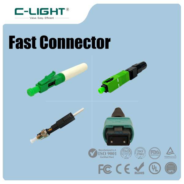
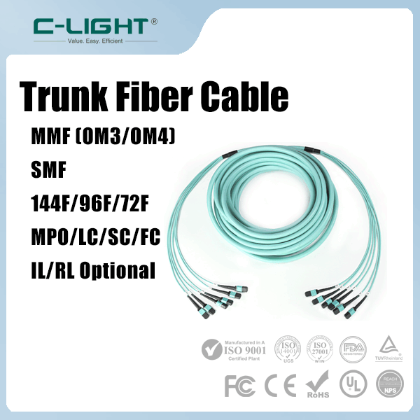
MPO/MTP fiber optic cables: High-density fiber connectivity for parallel-optics links and data center cabling infrastructure.
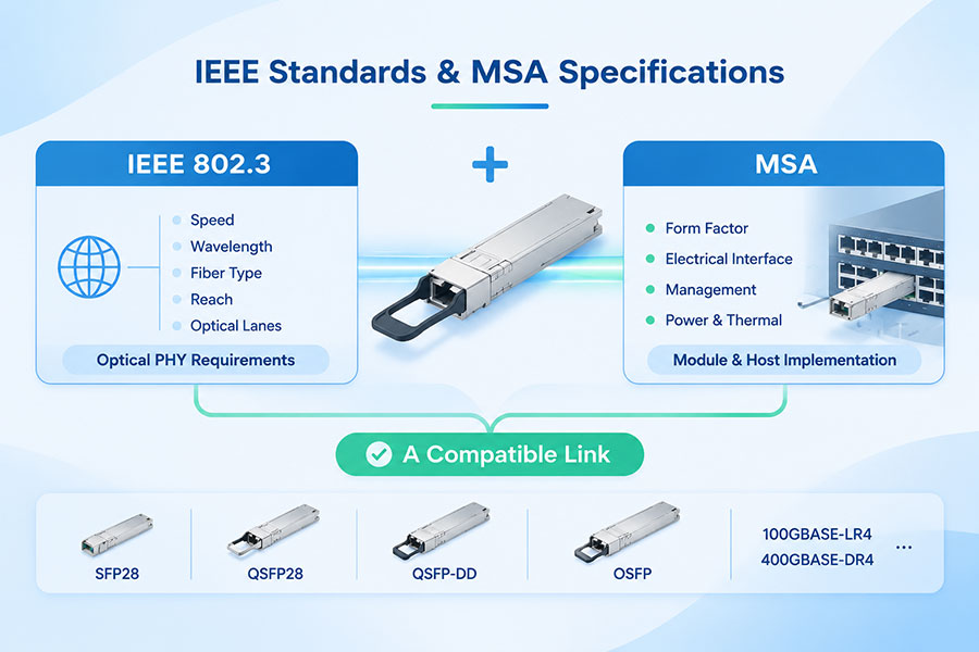
400G optical transceivers: Options for different data center architectures and transmission distances.
800G optical transceivers: High-bandwidth connectivity for AI clusters and next-generation data center networks.
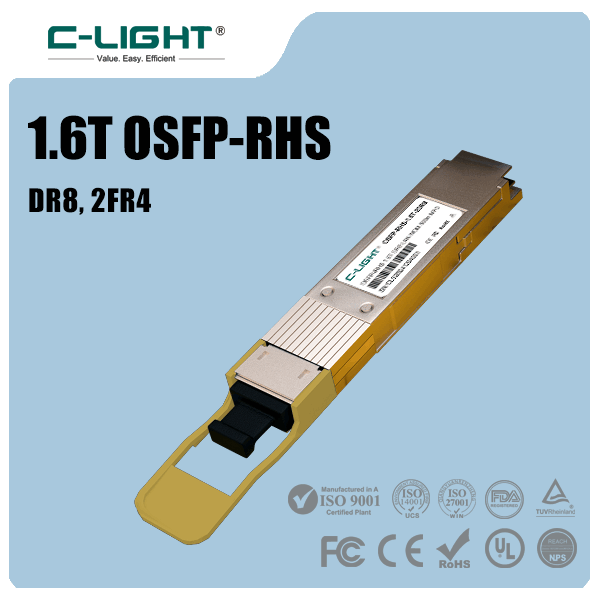
1.6T optical transceivers: Higher-capacity optical interfaces for emerging high-speed infrastructure.
Fiber optic connectivity components: Supporting optical distribution, interconnection, and network deployment requirements.
Correct connector selection, clean end faces, and suitable inspection procedures are important throughout the deployment process. For product specifications, compatibility requirements, or customized optical connectivity solutions, Contact C-LIGHT.
12. Conclusion
Fiber optic connector inspection is a fundamental quality-control step for reliable optical communication. Using a suitable inspection microscope, identifying contamination and physical defects, applying compatible cleaning methods, and reinspecting the end face can significantly reduce connector-related problems.
For modern data centers and telecom networks, inspection should cover every optical interface, including individual fibers in MPO/MTP connectors. Combined with insertion-loss and optical power testing, a consistent inspection process helps
 >

 >
 >
 >
 >
 >
 >
 >