TEL:+86 132 6656 7067


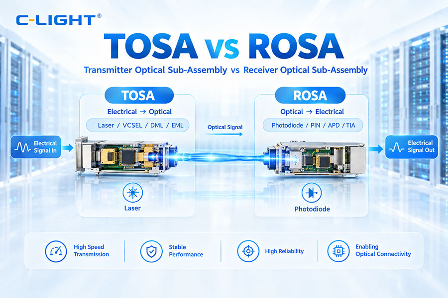
TOSA and ROSA are two fundamental optical subassemblies used inside fiber optic transceivers and optical communication equipment. TOSA stands for Transmitter Optical Sub-Assembly and is responsible for converting electrical signals into optical signals. ROSA stands for Receiver Optical Sub-Assembly and converts received optical signals back into electrical signals.
Although TOSA and ROSA perform opposite functions, both are essential to the operation of an optical transceiver. Their optical components, electrical interfaces, packaging methods, and performance characteristics vary according to the transmission speed, wavelength, reach, and application of the module.
In modern optical modules ranging from 1G and 10G to 25G, 100G, 400G, 800G, and higher-speed systems, the design of TOSA and ROSA has evolved significantly to support higher bandwidth, improved optical performance, and more demanding signal integrity requirements.
1. What Is TOSA?
TOSA stands for Transmitter Optical Sub-Assembly. It is the transmitting optical section of an optical transceiver and is designed to convert an electrical data signal into a modulated optical signal.
A typical TOSA contains a light source, optical coupling components, a laser package, and mechanical structures used to align and couple the optical output into the fiber or optical connector.
Depending on the module design, the light source may be a VCSEL, DML, EML, or another semiconductor laser technology. The choice depends on transmission speed, wavelength, optical reach, modulation method, and required power characteristics.
2. What Is ROSA?
ROSA stands for Receiver Optical Sub-Assembly. It is the receiving optical section of an optical transceiver and converts incoming optical signals into electrical signals.
A typical ROSA contains a photodetector and optical coupling structure. Common photodetector technologies include PIN photodiodes and avalanche photodiodes (APDs).
Depending on the design, the transimpedance amplifier (TIA) may be integrated with the photodetector assembly or implemented as a separate electrical component. The TIA converts the small current generated by the photodiode into a usable voltage signal for subsequent signal processing.
3. TOSA vs ROSA: Basic Difference
| Feature | TOSA | ROSA |
|---|---|---|
| Full Name | Transmitter Optical Sub-Assembly | Receiver Optical Sub-Assembly |
| Main Function | Electrical-to-optical conversion | Optical-to-electrical conversion |
| Core Device | Laser | Photodiode |
| Common Devices | VCSEL, DML, EML | PIN, APD |
| Typical Supporting Circuit | Laser driver | TIA |
| Signal Direction | Transmit | Receive |
| Main Output | Optical signal | Electrical signal |
The simplest way to understand the relationship is that TOSA generates the optical signal, while ROSA detects and converts the received optical signal.
4. How Does TOSA Work?
The TOSA transmission process begins with an electrical data signal generated by the host system or the module's electrical circuitry.
The electrical signal is supplied to the laser driver or modulation circuit.
The driver controls the laser current or modulation input.
The laser generates and modulates optical power.
The optical output is coupled through lenses or other optical structures.
The optical signal is launched into the fiber or optical interface.
The optical alignment inside the TOSA is critical. The laser output must be precisely coupled into the intended optical path to minimize coupling loss and maintain stable optical performance.
5. How Does ROSA Work?
The ROSA receiving process begins when the optical signal reaches the module through the fiber interface.
The incoming optical signal enters the optical coupling structure.
The photodiode detects the optical energy.
The photodiode converts optical power into photocurrent.
The TIA converts the small current into an electrical voltage signal.
The electrical signal is sent to the following signal-processing circuitry.
Receiver sensitivity is an important performance parameter because the ROSA must detect weak optical signals while maintaining an acceptable noise level and bit error ratio.
6. Main Components of a TOSA
A TOSA can contain several optical and mechanical components, depending on the design.
The primary component is the semiconductor laser. VCSELs are widely used for short-reach multimode applications, while DML and EML technologies are commonly used in single-mode systems with different reach and performance requirements.
Other components may include lenses, optical isolators, monitor photodiodes, submounts, ferrules, coupling structures, and hermetic or non-hermetic packaging.
The exact internal configuration depends on the module's wavelength, data rate, optical power, and transmission architecture.
7. Main Components of a ROSA
The main active component of a ROSA is the photodetector. PIN photodiodes are widely used because of their relatively simple structure, good linearity, and suitability for many optical communication applications.
APDs provide internal avalanche gain and can offer improved sensitivity for applications where the received optical signal is relatively weak.
A ROSA may also include optical filters, lenses, optical windows, alignment structures, and a TIA depending on the package and module architecture.
8. TOSA Laser Technologies
Different laser technologies can be used in TOSA assemblies.
| Laser Type | Typical Application | Typical Characteristics |
|---|---|---|
| VCSEL | Short-reach multimode links | Low-cost, high-speed short-distance transmission |
| DML | Single-mode optical links | Direct modulation and relatively simple structure |
| EML | Higher-speed and longer-reach links | High-speed modulation with improved transmission characteristics |
VCSELs are commonly associated with 850 nm multimode applications. DML and EML devices are frequently used in single-mode systems at wavelengths such as 1310 nm and 1550 nm.
9. PIN vs APD in ROSA
PIN and APD are the two major photodetector technologies used in optical receivers.
| Feature | PIN | APD |
|---|---|---|
| Structure | PIN photodiode | Avalanche photodiode |
| Internal Gain | No avalanche gain | Internal avalanche gain |
| Receiver Sensitivity | Suitable for many standard links | Can provide higher sensitivity |
| Bias Requirement | Lower | Higher |
| Complexity | Relatively simple | More complex |
| Typical Use | Many short and medium-reach applications | Applications requiring additional receiver sensitivity |
The choice between PIN and APD depends on link budget, required sensitivity, wavelength, reach, power budget, and module architecture.
10. Role of the Laser Driver and TIA
TOSA and ROSA are optical subassemblies, but their performance is closely related to supporting electronic components.
On the transmitter side, the laser driver provides the electrical current and modulation control required by the laser. It also helps define the electrical-to-optical response of the transmitter.
On the receiver side, the TIA amplifies the very small photocurrent generated by the photodiode and converts it into a voltage signal suitable for downstream processing.
The interaction between the optical subassembly and its supporting circuitry becomes increasingly important as data rates increase.
11. TOSA and ROSA in an Optical Transceiver
A conventional duplex optical transceiver contains both a transmit path and a receive path. The TOSA handles the transmit direction, while the ROSA handles the receive direction.
The host electrical interface sends data into the transmitter path. The TOSA converts the electrical signal to light and launches it into the optical fiber.
At the other end of the link, the receiving module's ROSA detects the incoming light and converts it back into an electrical signal for processing.
This creates the complete electrical-to-optical-to-electrical communication path.
12. TOSA and ROSA in BiDi Modules
BiDi optical modules use different wavelengths for upstream and downstream transmission over a single fiber. In these modules, the TOSA and ROSA operate on different optical wavelengths.
A wavelength-selective optical filter or WDM component is typically used to separate the transmit and receive optical paths.
This design allows bidirectional communication over a single fiber and reduces the number of fibers required for the link.
13. TOSA and ROSA for 10G Optical Modules
In 10G optical transceivers, the TOSA and ROSA are typically designed for approximately 10.3 Gb/s electrical and optical operation.
Short-reach 10G modules may use 850 nm VCSEL-based TOSA designs, while longer-reach single-mode modules can use 1310 nm DML or EML transmitters with suitable receiver technologies.
The exact optical configuration depends on the specific Ethernet standard and transmission distance.
14. TOSA and ROSA for 25G Optical Modules
25G optical modules increase the electrical and optical signaling rate compared with 10G systems. TOSA designs therefore require higher-speed laser modulation and tighter electrical-optical performance.
25G SR modules commonly use 850 nm VCSELs for multimode fiber. Longer-reach 25G solutions can use 1310 nm single-mode optics and different laser and receiver configurations.
As module speed increases, the electrical interface between the laser driver, TOSA, ROSA, and host system becomes more sensitive to signal integrity and component characteristics.
15. TOSA and ROSA in 100G Modules
100G optical modules can use multiple optical lanes or wavelength multiplexing depending on the optical standard.
In a parallel optical architecture, multiple TOSA and ROSA channels may be used to transmit and receive independent optical lanes. In wavelength-multiplexed architectures, multiple wavelengths can be combined through optical multiplexers and demultiplexers.
This makes the internal optical architecture of 100G modules more complex than that of single-channel lower-speed transceivers.
16. TOSA and ROSA in 400G and 800G Modules
At 400G and 800G, optical modules can contain multiple optical engines or multiple parallel optical channels. The exact implementation depends on the module architecture, optical PMD, wavelength plan, and reach.
Parallel solutions may use multiple TOSA and ROSA channels, while wavelength-multiplexed implementations can integrate several wavelengths within a smaller number of fiber interfaces.
As the number of channels and lane rates increase, the alignment, thermal management, optical coupling, and electrical signal integrity of the optical subassemblies become increasingly important.
17. TOSA and ROSA in PAM4 Modules
PAM4 is widely used in modern high-speed optical modules to increase the number of bits transmitted per symbol. It uses four optical or electrical signal levels to represent two bits per symbol.
For a PAM4 transmitter, the laser and TOSA must accurately reproduce the required multi-level optical modulation. The receiver side must detect these signal levels with sufficient linearity and signal-to-noise performance.
Therefore, PAM4 designs place greater demands on both TOSA and ROSA performance than conventional NRZ architectures.
18. TOSA and ROSA for 1310nm and 1550nm Systems
Different optical communication wavelengths require different semiconductor devices and optical components.
1310 nm is widely used in many single-mode data center and Ethernet applications because of its favorable transmission characteristics over standard single-mode fiber.
1550 nm is commonly used in longer-reach and wavelength-division multiplexing systems because of the low fiber attenuation around the 1550 nm region and the compatibility of many optical components with DWDM applications.
The wavelength influences the choice of laser, photodiode, optical filter, coupling structure, and other components in the TOSA and ROSA.
19. TOSA and ROSA Packaging
Packaging is critical because optical coupling requires precise alignment between the optical components.
Packaging structures must provide mechanical stability, thermal performance, electrical connections, and optical alignment. Depending on the application, TOSA and ROSA assemblies can use different package styles and fiber coupling methods.
As transmission speeds increase, packaging tolerances become more demanding because optical alignment, parasitic effects, thermal expansion, and high-frequency electrical connections can affect overall module performance.
20. Optical Coupling and Alignment
Efficient coupling between the laser and fiber is one of the key performance factors in a TOSA. Misalignment can increase coupling loss and reduce transmitter output power.
On the receiver side, the optical signal must be efficiently focused onto the photodetector. Poor optical alignment can reduce received power and adversely affect receiver sensitivity.
Precision alignment therefore plays an important role in both assembly yield and long-term reliability.
21. TOSA and ROSA Performance Parameters
Different performance parameters are used to evaluate TOSA and ROSA assemblies.
| TOSA Parameters | ROSA Parameters |
|---|---|
| Optical output power | Receiver sensitivity |
| Center wavelength | Responsivity |
| Spectral characteristics | Bandwidth |
| Extinction ratio | Optical overload |
| RIN | Noise characteristics |
| Rise and fall time | Bit error performance |
The required values depend on the optical standard and module application.
22. TOSA and ROSA Reliability
Optical subassemblies must maintain stable performance over temperature, operating time, and environmental changes.
Laser wavelength, output power, photodiode response, optical alignment, and electrical characteristics can all change with temperature. Thermal design and compensation are therefore important aspects of module reliability.
Manufacturing processes must also control optical alignment, soldering, bonding, contamination, and mechanical stress to maintain consistent performance.
23. TOSA vs ROSA: Key Differences
| Item | TOSA | ROSA |
|---|---|---|
| Function | Transmit optical signals | Receive optical signals |
| Conversion | Electrical to optical | Optical to electrical |
| Main Active Device | Laser | Photodiode |
| Common Technologies | VCSEL / DML / EML | PIN / APD |
| Supporting Circuit | Laser driver | TIA |
| Main Performance Focus | Output power and optical modulation | Sensitivity and detection performance |
| Typical Position | Transmitter side | Receiver side |
24. TOSA vs ROSA vs BOSA
TOSA and ROSA are normally used for separate transmit and receive functions. BOSA, or Bi-directional Optical Sub-Assembly, combines transmitting and receiving functions into one optical assembly for bidirectional applications.
A BOSA typically integrates a transmitter, receiver, and wavelength-separation optical components so that two optical directions can share a single fiber.
This architecture is common in PON and other bidirectional optical communication systems.
25. Why TOSA and ROSA Matter in Optical Module Design
TOSA and ROSA form the optical foundation of many pluggable transceivers. Even when the module uses an advanced DSP, the quality of the underlying transmitter and receiver optical assemblies still directly affects the optical link.
For high-speed applications, laser modulation performance, photodiode bandwidth, optical coupling efficiency, thermal stability, and packaging precision all contribute to the final module performance.
This is why optical subassembly design, component selection, and manufacturing control remain important even as more signal-processing functions move into integrated electronic devices.
26. How to Choose TOSA and ROSA Components
The selection of TOSA and ROSA components should start with the target optical standard and transmission speed.
The next considerations include wavelength, transmission distance, fiber type, required optical power, receiver sensitivity, optical budget, modulation technology, and operating temperature.
For high-speed modules, electrical bandwidth, thermal performance, optical coupling, and package design should also be evaluated together.
Using a TOSA or ROSA that meets the nominal wavelength and data rate is not enough if the optical subassembly is not matched to the complete transceiver architecture.
27. TOSA and ROSA in High-Speed Optical Communication
The transition from 10G to 25G, 100G, 400G, 800G, and 1.6T has increased the technical requirements placed on optical subassemblies.
Higher speeds require faster lasers and photodetectors, improved optical alignment, tighter package tolerances, better electrical interfaces, and more effective thermal control.
For AI data centers and high-performance networks, these requirements are particularly important because large numbers of optical modules can operate simultaneously at high bandwidth.
28. Conclusion
TOSA and ROSA are fundamental optical subassemblies used in fiber optic transceivers. TOSA converts electrical signals into optical signals using laser-based technology, while ROSA converts incoming optical signals into electrical signals using photodetectors and associated receiver circuitry.
The two assemblies use different core components and have different performance requirements, but both are essential to reliable optical transmission. TOSA performance is strongly related to optical output, modulation, wavelength, and coupling efficiency, while ROSA performance depends on sensitivity, bandwidth, responsivity, noise, and detection efficiency.
As optical communication continues to move toward 400G, 800G, 1.6T, and beyond, the design and manufacturing of TOSA and ROSA assemblies will remain important for achieving higher bandwidth, longer reach, and stable optical performance.
 >
>

 >
>
 >
>
 >
>
 >
>
 >
>
 >
>
 >
>