TEL:+86 132 6656 7067


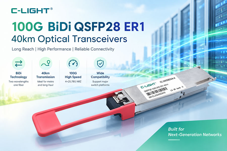
As data center interconnections, enterprise backbones, and telecommunications networks require higher capacity over existing fiber infrastructure, 100G optical transceivers provide a practical option for long-reach Ethernet connectivity. The C-LIGHT 100G BiDi QSFP28 ER1 40km optical transceiver, model CL100GQBDER1-40-A, is designed for 100GBASE-ER1-40 BIDI applications over single-mode fiber (SMF), with a specified transmission distance of up to 40 km.
Unlike conventional duplex-fiber optical links, a bidirectional (BiDi) transceiver uses different transmit and receive wavelengths to support communication over a single optical fiber. This architecture can reduce fiber-strand requirements while supporting high-capacity connectivity between compatible network devices.
The CL100GQBDER1-40-A features a QSFP28 package, a simplex LC optical connector, PAM4 optical signaling, an EML laser, an APD receiver, and integrated digital diagnostic monitoring. Its design supports applications that need 100GbE connectivity over longer single-mode fiber links, subject to compatible endpoint equipment and a properly engineered optical link budget.
1. Product Overview and Key Features
The CL100GQBDER1-40-A combines a compact QSFP28 form factor with single-fiber bidirectional transmission for 100G long-reach connectivity. Its wavelength configuration separates transmit and receive signals, allowing both directions to use the same optical fiber when paired with a compatible far-end transceiver.
Key Product Features
100G Ethernet connectivity: Designed for 100GBASE-ER1-40 BIDI applications.
Transmission distance: Supports links up to 40 km over suitable single-mode fiber.
Bidirectional transmission: Uses a simplex LC connector and different transmit and receive wavelengths.
PAM4 optical signaling: Uses a 106.25 Gb/s optical lane signaling rate.
Electrical interface: Supports a 4 × 25.78 Gb/s NRZ electrical interface using CAUI-4.
Optical components: Uses an EML laser and an APD receiver.
Digital monitoring: Provides an I2C management interface with integrated digital diagnostic monitoring.
Power design: Operates from a single +3.3 V power supply, with maximum power consumption specified at 4.5 W.
Operating temperature: Supports a case temperature range of 0°C to +70°C.
2. Technical Specifications
The following table summarizes the main parameters provided in the C-LIGHT product datasheet.
| Parameter | Specification |
|---|---|
| Product model | CL100GQBDER1-40-A |
| Product type | 100G BiDi QSFP28 ER1 40km optical transceiver |
| Application | 100GBASE-ER1-40 BIDI |
| Data rate listed in datasheet | 106.25 Gb/s |
| Optical modulation | PAM4 |
| Electrical interface | 4 × 25.78 Gb/s NRZ, CAUI-4 |
| Transmission distance | Up to 40 km |
| Fiber type | Single-mode fiber (SMF) |
| Transmit center wavelength | 1304.58 nm typical |
| Receive center wavelength | 1309.14 nm typical |
| Optical connector | Simplex LC |
| Laser | EML |
| Receiver | APD |
| Supply voltage | Single +3.3 V supply |
| Maximum power consumption | 4.5 W |
| Operating case temperature | 0°C to +70°C |
| Digital monitoring | I2C interface with integrated DDMI |
| Management and package standards | SFF-8636 and SFF-8679, as listed in the datasheet |
The module combines high-speed PAM4 optical transmission with a four-lane NRZ electrical interface. When evaluating equipment compatibility, distinguish the 106.25 Gb/s optical signaling rate from the electrical lane configuration and confirm support for the specified 100G BiDi application at both ends.
3. How 100G BiDi Single-Fiber Transmission Works
Traditional duplex optical connections commonly use one fiber for transmitting data and a second fiber for receiving it. BiDi technology uses different optical wavelengths for the two transmission directions, enabling bidirectional communication through a single fiber strand.
For the CL100GQBDER1-40-A, the datasheet specifies a typical transmit center wavelength of 1304.58 nm and a typical receive center wavelength of 1309.14 nm. The module transmits at one wavelength while receiving signals at the other.
Simplex LC Connectivity
A simplex LC connector accommodates a single optical fiber, unlike a duplex connector arrangement that uses two fibers. This can reduce the number of fiber strands needed for a link and help preserve spare fiber capacity in existing installations.
However, single-fiber operation requires the equipment at the opposite end to use a complementary transmit and receive wavelength arrangement. Two modules should not be assumed to form a valid BiDi link simply because both are labeled 100G or QSFP28.
Before deployment, verify the far-end module's transmit wavelength, receive wavelength, supported distance, optical power range, and interface compatibility. The entire link must support the intended bidirectional wavelength plan.
4. 40 km Transmission over Single-Mode Fiber
The CL100GQBDER1-40-A is specified for transmission distances up to 40 km over single-mode fiber. SMF is suitable for long-reach optical communication because it supports optical transmission across distances that exceed the typical reach of many short-reach multimode applications.
A 40 km link may be relevant to metropolitan network connections, telecommunications infrastructure, remote aggregation sites, and data center interconnections where the endpoints are separated by a substantial distance.
Optical Link Budget and Deployment Conditions
The stated 40 km reach is not a guarantee that every installed 40 km fiber path will operate correctly. Actual performance depends on the combined optical characteristics of the transceivers and the installed link.
Before installation, evaluate the following factors:
Fiber attenuation: Confirm that the total fiber loss remains within the supported optical budget.
Connector and splice loss: Account for connection points, patch panels, and any splices along the route.
Transmit and receive power: Verify that received optical power remains within the module's specified operating range.
Far-end wavelength compatibility: Use a compatible BiDi counterpart with the appropriate wavelength arrangement.
Optical path condition: Inspect and clean connectors and verify the condition of the fiber before testing.
Host interoperability: Check that the switch, router, or other host equipment supports the module's form factor and intended interface.
5. PAM4 Signaling, Electrical Interface, and Optical Components
PAM4 Optical Signaling
The transceiver uses PAM4 optical signaling at a specified lane signaling rate of 106.25 Gb/s. PAM4 represents four signal levels, allowing two bits of information to be conveyed per symbol. This supports high data rates without requiring the same symbol rate as a two-level signaling scheme carrying one bit per symbol.
Higher-order signaling places greater importance on signal quality, noise tolerance, and optical performance. Link design and equipment compatibility must therefore follow the selected transceiver's specifications rather than relying only on the nominal data rate.
Four-Lane NRZ Electrical Interface
The datasheet specifies a 4 × 25.78 Gb/s NRZ electrical interface using CAUI-4. This describes the electrical connection between the host system and the module, while the optical side uses PAM4 signaling.
The distinction matters when selecting a module for a switch or router. The host must support the appropriate QSFP28 form factor and the intended 100G interface. Correct physical fit alone does not guarantee interoperability with every host port, firmware configuration, or networking platform.
EML Laser and APD Receiver
The transceiver uses an electro-absorption modulated laser (EML) for optical transmission and an avalanche photodiode (APD) receiver for optical detection. These components are part of the module's optical design for its specified long-reach application.
For system planning, the complete optical transmitter and receiver specifications remain important. The selected far-end module, fiber condition, connector losses, and received signal level must collectively support reliable link operation.
6. Optical Transmitter and Receiver Specifications
The following values are drawn from the product datasheet. Transmitter and receiver limits should be assessed in the context of the complete link specification rather than interpreted as independent guarantees of 40 km reach.
Transmitter Optical Specifications
| Parameter | Symbol | Minimum | Typical | Maximum | Unit |
|---|---|---|---|---|---|
| Center wavelength | CW | 1303.54 | 1304.58 | 1305.63 | nm |
| Average launch power | PTX | 1.7 | — | 7.1 | dBm |
| Outer optical modulation amplitude (OMA) | OMA | Conditional on TDECQ | — | 7.9 | dBm |
| Side-mode suppression ratio | SMSR | 30 | — | — | dB |
| Extinction ratio | ER | 5 | — | — | dB |
The datasheet gives conditional OMA minimum values based on transmitter and dispersion eye closure for PAM4 (TDECQ). Consult the original optical specification table when using these limits for detailed engineering or acceptance testing.
Receiver Optical Specifications
| Parameter | Symbol | Minimum | Typical | Maximum | Unit |
|---|---|---|---|---|---|
| Center wavelength | CW | 1308.09 | 1309.14 | 1310.19 | nm |
| Average receive power | PRX | -16 | — | -3.4 | dBm |
| Receive power, OMA | POMA | — | — | -2.6 | dBm |
| Receiver sensitivity, outer OMA | SEN_OMA | Conditional on TDECQ | — | Conditional on TDECQ | dBm |
| Loss-of-signal assert threshold | LosA | -26 | — | — | dBm |
| Loss-of-signal de-assert threshold | LosDA | — | — | -17 | dBm |
| Loss-of-signal hysteresis | LosH | 0.5 | — | — | dB |
Receiver sensitivity is defined with reference to the applicable TDECQ test conditions in the datasheet. For formal qualification or link engineering, use the complete source specification, including its conditional sensitivity limits and test notes.
7. Power Consumption, Monitoring, and Host Compatibility
Low-Voltage Power Design
The CL100GQBDER1-40-A uses a single +3.3 V power supply and has a maximum power consumption of 4.5 W according to the datasheet. Power requirements should be checked against the host device's supported optical-module power budget, especially when multiple high-speed modules operate simultaneously.
Thermal conditions inside a switch or router can affect module operation. Ensure that the host platform provides appropriate airflow and supports the module's specified operating case temperature of 0°C to +70°C.
Digital Diagnostic Monitoring
The module includes an I2C interface with integrated digital diagnostic monitoring (DDMI). Supported monitoring functions can help network operators inspect module status and troubleshoot optical links, subject to the data fields and management support exposed by the host system.
During commissioning and maintenance, operators should review the monitoring information available from both ends of the link and compare it with the transceiver's operating limits. Abnormal received power, temperature, or other supported diagnostic readings can help identify conditions that require further inspection.
Standards and Compatibility Checks
The product datasheet lists compliance with IEEE 802.3bm, 100G Lambda MSA, SFF-8636, and SFF-8679, as well as the EU Directive 2015/863/EU. For purchasing and network integration, confirm the precise supported interface and standards revision with the supplier and host-device documentation.
Before ordering, verify the following items:
Host port compatibility with the QSFP28 form factor and intended 100G BiDi application.
Support for the specified optical interface and 40 km reach.
Compatible transmit and receive wavelength configuration at the far end.
Available module power budget and operating airflow.
Required monitoring support, firmware compatibility, and network platform configuration.
8. Typical Applications and Deployment Scenarios
Telecommunications and Metropolitan Networks
Telecommunications infrastructure often needs high-capacity connections between aggregation points, remote facilities, and network nodes over substantial distances. A 100G BiDi transceiver rated for 40 km can be considered for suitable single-mode fiber paths where its interface and optical budget meet the network requirements.
Data Center Interconnections
Some data center networks require 100GbE links between facilities or aggregation locations that are separated beyond the reach of shorter-distance optical modules. The 40 km reach rating makes this transceiver relevant to such long-reach applications, provided that the fiber plant, endpoints, and optical interface are compatible.
Enterprise and Campus Backbone Links
Large enterprise and campus networks may use long-distance fiber links to connect separate buildings, remote network rooms, or distributed infrastructure. Single-fiber BiDi transmission can be useful where fiber-strand availability is limited, particularly when compatible BiDi equipment is already supported by the network architecture.
Fiber-Strand Utilization
Where a route has limited spare fiber, single-fiber bidirectional transmission can reduce the strand count required for a link compared with a conventional two-fiber arrangement. This can support more efficient use of existing cabling infrastructure, although actual savings depend on the overall wavelength plan and endpoint design.
Across these applications, the transceiver's advertised reach should be treated as a supported design capability, not a substitute for validating the physical path, endpoint compatibility, and total optical loss.
9. Conclusion
The C-LIGHT CL100GQBDER1-40-A 100G BiDi QSFP28 ER1 40km optical transceiver is designed for high-capacity Ethernet links over single-mode fiber. Its key features include a QSFP28 package, simplex LC connectivity, 1304.58 nm typical transmit wavelength, 1309.14 nm typical receive wavelength, PAM4 optical signaling, EML laser, APD receiver, and integrated digital diagnostic monitoring.
By carrying transmit and receive signals on different wavelengths over a single fiber strand, BiDi technology can reduce fiber-strand requirements for compatible long-reach links. The module's specified reach of up to 40 km makes it relevant to telecommunications transport, data center interconnections, and enterprise backbone deployments that require 100G connectivity.
Successful deployment depends on more than the nominal data rate and transmission distance. Network planners should confirm the complementary far-end wavelength configuration, host-device compatibility, power and thermal requirements, optical link budget, and monitoring support. These checks help determine whether the transceiver is appropriate for the target network.
 >
>

 >
>
 >
>
 >
>
 >
>
 >
>
 >
>
 >
>