TEL:+86 132 6656 7067


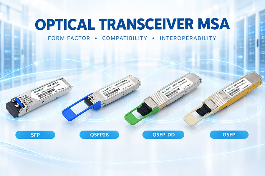
Optical transceiver modules are used across a wide range of networking systems, from enterprise switches and telecom equipment to 400G, 800G, and 1.6T data center platforms. As the number of manufacturers and module types increased, the industry needed common mechanical and electrical requirements to make pluggable modules easier to design, manufacture, and deploy. Multi-Source Agreements, commonly known as MSAs, were developed to address this requirement.
An Optical Transceiver MSA is an industry specification created by multiple companies to define common requirements for a particular module or interface family. Depending on the MSA, these requirements can cover mechanical dimensions, cage and connector interfaces, electrical pin assignments, thermal behavior, low-speed control signals, management functions, and optical connector configurations. The exact scope varies between different MSAs.
It is important to understand that an MSA is not necessarily the same as an Ethernet or optical transmission standard. For example, the QSFP-DD MSA defines the module and host interface, while optical signaling specifications are defined by applicable industry standards outside the MSA.
1. What Is an Optical Transceiver MSA?
MSA stands for Multi-Source Agreement. In the optical communications industry, an MSA is an agreement or specification developed by multiple companies to establish a common interface for a class of pluggable modules.
The purpose is to allow different manufacturers to build products around the same basic mechanical and electrical requirements. This creates a common ecosystem rather than requiring every module vendor to develop a completely proprietary interface.
Different MSA specifications can focus on different generations and form factors. Examples include SFP-family specifications, QSFP-family specifications, QSFP-DD, and OSFP.
2. Why Are MSAs Important?
Without a common interface specification, an optical module designed by one manufacturer might require a unique cage, connector, pinout, or management system in the host equipment.
An MSA establishes common design requirements so that equipment manufacturers and transceiver suppliers can work from the same interface definition. This can reduce mechanical and electrical uncertainty and make multi-vendor product development more practical.
For network operators, an established MSA ecosystem can also provide more choice when selecting compatible modules, cables, and network equipment.
3. What Does an Optical Transceiver MSA Define?
The exact contents of an MSA depend on the specific specification, but a form-factor MSA can define several major areas.
| Area | Typical Definition |
|---|---|
| Mechanical | Module dimensions, cage dimensions, connector mating, latching, and mounting requirements |
| Electrical | Pin assignments, high-speed lanes, control signals, power, and host electrical requirements |
| Thermal | Module temperature limits, heat-sink requirements, airflow considerations, and related mechanical provisions |
| Management | Low-speed interface, timing, identification, monitoring, and module management requirements |
| Optical Interface | Connector types, lane assignments, and optical interface configurations where included |
| Environmental | ESD, operating conditions, and related requirements where covered by the specification |
The scope can vary significantly. The QSFP-DD hardware specification, for example, covers electrical interfaces, optical interfaces and lane assignments, mechanical requirements, thermal requirements, ESD references, and timing requirements for management functions.
4. What Does an MSA Usually Not Define?
A common misunderstanding is that an MSA defines the complete optical performance of a transceiver. In many cases, it does not.
The form-factor MSA may define the physical optical interface and lane mapping while leaving the optical signaling and transmission performance to separate standards. The QSFP-DD specification explicitly states that optical signaling specifications are not included in its hardware specification and are instead defined by applicable industry standards.
This distinction is important because several different optical standards can use the same module form factor.
5. MSA vs Ethernet Standard
An MSA and an Ethernet standard solve different problems.
An Ethernet standard such as IEEE 802.3 defines networking functions and physical-layer specifications for particular Ethernet rates and media. IEEE 802.3df-2024, for example, adds physical-layer and management parameters for 400 Gb/s and 800 Gb/s Ethernet operation.
A module MSA, by contrast, primarily defines the interface used to package and connect the transceiver to the host system.
In practical terms, an optical module can therefore comply with both a form-factor MSA and an Ethernet standard. The MSA defines how the module fits and communicates with the host, while the optical or Ethernet standard defines how the data is transmitted over the physical link.
6. MSA vs Optical PMD
PMD, or Physical Medium Dependent, describes the optical or physical transmission characteristics of a particular link implementation. A PMD may specify wavelength, fiber type, modulation, reach, optical power, receiver requirements, and other transmission parameters.
The same form factor can support multiple PMDs. For example, a high-speed pluggable module family may include short-reach multimode, parallel single-mode, or wavelength-multiplexed variants.
This is why terms such as "QSFP-DD" and "800G DR8" should not be treated as equivalent. QSFP-DD identifies a form-factor ecosystem, while DR8 identifies a particular optical application.
7. SFP MSA
The SFP family is one of the most established examples of standardized pluggable transceiver architecture. Its development established a compact module approach that became widely adopted in Ethernet, storage, telecom, and industrial networking.
SFP-family specifications cover areas such as the electrical interface, module dimensions, management, and connector requirements through related industry specifications.
The long adoption history of the SFP ecosystem also demonstrates the value of a common physical interface: different optical standards and network speeds can be implemented using closely related module packaging.
8. QSFP MSA
QSFP extends the concept to a higher-density module with multiple high-speed electrical lanes. The QSFP ecosystem has been used for 40G, 100G, 200G, and other networking generations through different electrical and optical implementations.
Management specifications such as SFF-8636 are used for four-lane pluggable module management. The current SFF specification list identifies SFF-8636 as the management interface for 4-lane modules and cables.
The QSFP family provides the architectural foundation from which later high-density form factors evolved.
9. QSFP-DD MSA
QSFP-DD stands for Quad Small Form-factor Pluggable Double Density. Its defining concept is an interface supporting up to eight high-speed electrical lanes while retaining a compact QSFP-derived mechanical architecture.
The current QSFP-DD hardware specification covers QSFP-DD, QSFP-DD800, and QSFP-DD1600. It defines electrical interfaces, optical lane assignments, connector and cage mechanics, thermal requirements, management timing, and other host/module requirements.
The same specification also identifies QSFP-DD800 as an enhanced form factor for 100 Gb/s-class per-lane operation and QSFP-DD1600 for 200 Gb/s-class per-lane operation.
10. OSFP MSA
OSFP stands for Octal Small Form Factor Pluggable. Like QSFP-DD, it uses an eight-lane high-speed electrical architecture, but its mechanical design is different.
The OSFP MSA has evolved through several revisions. The current published OSFP specification is Rev. 5.22, dated August 14, 2025. The specification covers OSFP, OSFP800, OSFP1600, and related mechanical and thermal variants.
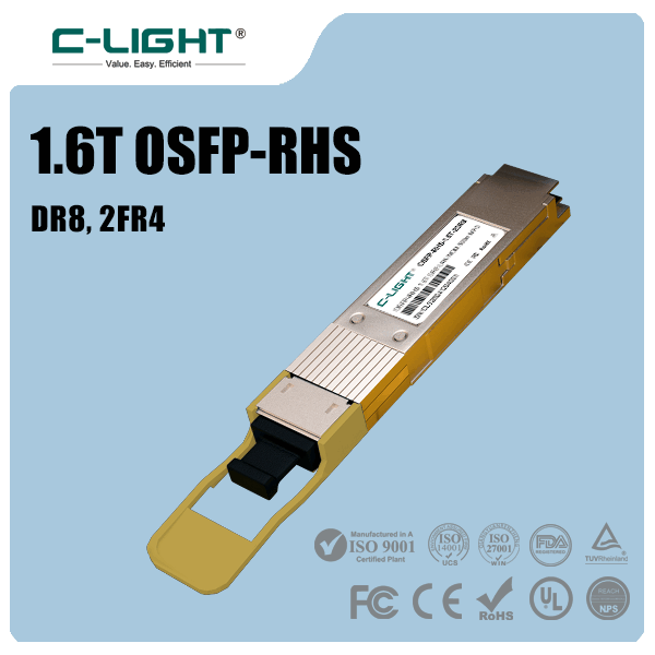
The OSFP ecosystem includes standard OSFP modules with integrated heat sinks as well as OSFP-RHS variants that use a host-side riding heat sink. These options reflect the increasing thermal requirements of higher-speed modules.
11. Form Factor MSA vs Optical Technology
One form factor can support multiple optical technologies. This is one of the most important concepts when working with optical transceiver specifications.
| Form Factor | Possible Optical Technologies | Typical Network Generations |
|---|---|---|
| SFP | VCSEL, DML, and other optical implementations | 1G-class and other applications |
| SFP+ | VCSEL, DML, EML and related implementations | 10G-class |
| SFP28 | VCSEL, DML, EML and related implementations | 25G-class |
| QSFP28 | Parallel optics and wavelength-multiplexed optics | 100G-class |
| QSFP-DD | Parallel, duplex, and other optical architectures | 400G / 800G / 1.6T |
| OSFP | Parallel, wavelength-multiplexed, and other optical architectures | 400G / 800G / 1.6T |
The form factor therefore describes the interface framework, not a single laser, wavelength, or transmission distance.
12. MSA and Electrical Lane Architecture
As optical transceiver speeds increase, electrical lane architecture becomes a major part of the MSA design.
Older modules may use one or four lower-speed electrical lanes, while modern 800G and 1.6T modules can use eight very-high-speed electrical lanes. Increasing the lane rate allows aggregate bandwidth to scale without continuously increasing the physical lane count.
This approach is used by both QSFP-DD and OSFP, which have evolved toward 112G-class and 224G-class electrical signaling generations.
13. MSA and PAM4
Higher-speed modules increasingly use PAM4 signaling to improve bandwidth efficiency. PAM4 provides four signal levels and carries two bits per symbol.
However, PAM4 also reduces the voltage separation between signal levels compared with NRZ. This increases the importance of electrical channel loss, noise, crosstalk, reflections, and equalization.
As a result, modern form-factor specifications have to account for increasingly demanding host electrical channels, connector performance, and signal-integrity requirements.
14. MSA and Signal Integrity
Signal integrity is not determined by the optical module alone. The complete electrical path includes the switch ASIC, package, PCB traces, vias, cage, connector, module contacts, and internal module electronics.
A form-factor MSA helps define the interface conditions under which these components must operate. Mechanical dimensions and connector specifications become increasingly important as electrical lane rates rise.
The QSFP-DD specification includes host PCB layout requirements, connector performance, high-speed electrical interfaces, and mechanical requirements to address these system-level considerations.
15. MSA and Thermal Management
Higher-speed optical modules generally require more attention to thermal management. Active components such as DSPs, optical engines, laser drivers, and retimers can increase module power.
As a result, modern MSAs include increasingly detailed thermal and mechanical requirements. QSFP-DD defines thermal requirements and provides additional high-power mechanical enhancements for QSFP-DD1600.
OSFP similarly incorporates thermal considerations into its mechanical architecture. The current OSFP specification also includes high-flow heat-sink examples and specific provisions for high-power modules.
16. MSA and Module Management
Modern optical modules need a management interface in addition to high-speed transmit and receive lanes. The host system must be able to identify the module, retrieve status information, monitor operating conditions, and in some cases configure module functions.
CMIS, or Common Management Interface Specification, is designed for this purpose and can be used by pluggable and on-board modules including QSFP-DD, OSFP, QSFP, and other module families.
The QSFP-DD hardware specification states that the memory maps for QSFP-DD, QSFP-DD800, and QSFP-DD1600 are based on CMIS.
17. MSA and Module Identification
Module identification allows the host system to determine what type of transceiver has been inserted and which management or memory-map behavior should be used.
Reference coding specifications such as SFF-8024 provide standardized identifiers for module types, connector types, encoding values, compliance codes, and other information used to interpret self-identifying modules. The current SFF-8024 revision is listed by SNIA as Rev. 4.14, published in June 2026.
This identification layer is important in multi-speed environments where the same physical host platform may support different module generations.
18. MSA and Optical Connector Configurations
Modern optical transceivers can use different connector structures depending on their optical architecture. Duplex LC connectors are common for two-fiber wavelength-multiplexed applications, while MPO/MTP® connectors are widely used for parallel optical channels.
High-speed MSAs can define or reference connector and lane-assignment requirements so that the module, connector, and host system operate as a coordinated interface.
For example, the QSFP-DD hardware specification includes optical interfaces, receptacles, mating fiber plugs, and breakout cable applications.
19. MSA and Breakout Applications
High-density modules can support breakout architectures in which one higher-bandwidth host interface is divided into multiple lower-speed connections.
This requires coordination between electrical lane mapping, optical channel mapping, module management, cable wiring, and host software.
The ability to define standard lane assignments within an MSA helps manufacturers design interoperable breakout cables and modules around a common interface.
20. MSA and Interoperability
MSA compliance can improve interoperability, but it should not be interpreted as a guarantee that every module will work in every network device.
A complete link also depends on the host switch, firmware, electrical signaling mode, supported optical PMD, module coding, power class, thermal conditions, and management implementation.
For example, a module can be mechanically compatible with a port while still failing to operate because the host does not support the required electrical rate or optical application.
21. Physical Compatibility vs Functional Compatibility
Physical compatibility means that the module can be inserted into the cage and connector correctly. Functional compatibility is broader and requires the host and module to support the required electrical, optical, management, and operational characteristics.
| Compatibility Layer | What to Check |
|---|---|
| Mechanical | Module size, cage, connector, latching, and mating |
| Electrical | Lane rate, signaling, pinout, power, and host channel |
| Optical | PMD, wavelength, fiber type, connector, and link budget |
| Management | CMIS, memory map, identification, and supported functions |
| Software | Firmware, module coding, port configuration, and platform restrictions |
| Thermal | Module power, airflow, heat sink, and chassis capability |
22. MSA and Multi-Vendor Networks
One of the main purposes of a multi-source architecture is to allow multiple manufacturers to develop products around a common interface.
This is useful in large network deployments because operators may source optical modules, cables, and equipment from different suppliers while maintaining a common physical platform.
However, multi-vendor interoperability still requires validation. Coding restrictions, firmware behavior, optical performance, and vendor-specific platform requirements can exist even when products follow the same underlying MSA.
23. Why MSA Revisions Matter
MSAs evolve as networking technology changes. New revisions may introduce higher electrical speeds, improved thermal structures, new connector configurations, additional optical lane mappings, or corrections to previous mechanical requirements.
The QSFP-DD MSA specification page lists successive hardware revisions for QSFP-DD, QSFP-DD800, and QSFP-DD1600, while the OSFP MSA specification page lists multiple revisions through Rev. 5.22.
When designing or purchasing a module, it is therefore useful to identify the exact specification revision relevant to the host platform and module generation.
24. MSA, Industry Standards, and Product Specifications
Three layers are often involved when defining an optical transceiver.
| Layer | Primary Role |
|---|---|
| Form Factor MSA | Defines module, cage, connector, electrical, mechanical, thermal, and management interface requirements |
| Industry Optical / Ethernet Standard | Defines transmission characteristics, PMD behavior, reach, and protocol-related requirements |
| Manufacturer Product Specification | Defines the specific module's wavelength, power, sensitivity, reach, temperature, coding, and other implementation details |
These layers work together. Looking at only one of them can result in an incomplete understanding of module compatibility or optical performance.
25. MSA for Optical Module Manufacturers
For optical module manufacturers, an MSA provides a common framework for designing modules that can fit standardized host systems.
Engineers can focus on the optical architecture, electrical implementation, thermal design, firmware, and manufacturing process without having to invent a completely different physical interface for each customer.
This is particularly valuable for manufacturers producing multiple generations of modules across different speed levels.
26. MSA for Network Equipment Manufacturers
For switch and router manufacturers, an MSA provides a defined host-side interface for cages, connectors, PCB routing, electrical lanes, management, and thermal integration.
The standardized interface helps equipment manufacturers build platforms that can accommodate a broad range of compatible modules.
At higher speeds, the host implementation becomes increasingly important because the switch PCB, connector, cage, airflow, and firmware all contribute to final system behavior.
27. MSA for Network Operators
Network operators benefit from standardized module ecosystems because they can select from a wider range of compatible products and can plan upgrades around established form-factor families.
However, operators should verify compatibility at the system level rather than relying only on the module label. The required speed, optical standard, reach, fiber infrastructure, power, coding, and host support should all be checked.
28. How to Read an Optical Transceiver Specification
When evaluating a transceiver, start by identifying the form factor, such as SFP, SFP28, QSFP28, QSFP-DD, or OSFP.
Next, identify the applicable optical or Ethernet standard and determine the optical configuration, including wavelength, fiber type, connector, and reach.
Finally, check the electrical interface, power class, management interface, coding, operating temperature, and host compatibility.
This method prevents the common mistake of treating the module's form factor or nominal data rate as a complete technical specification.
29. Future Development of Optical Transceiver MSAs
The development of optical transceiver MSAs continues to follow the increase in network bandwidth and module complexity.
Higher electrical lane rates require improvements in connectors, PCB materials, signal integrity, thermal structures, module packaging, and management systems.
The emergence of 800G and 1.6T modules demonstrates that the role of an MSA is expanding from basic mechanical compatibility toward highly detailed electrical, thermal, optical-interface, and management requirements.
30. Conclusion
Optical Transceiver MSAs provide a common framework for developing interoperable pluggable modules and host interfaces. They can define mechanical dimensions, electrical interfaces, connector systems, thermal requirements, management functions, and other interface characteristics depending on the specific MSA.
The most important point is that an MSA is not necessarily the same thing as an optical transmission standard. A form-factor MSA defines how a module interfaces with the host, while Ethernet and optical standards define how data is transmitted across the physical link. The QSFP-DD specification explicitly separates its form-factor requirements from optical signaling specifications, and CMIS provides a common management framework used by several pluggable module families.
Understanding the relationship between MSA specifications, optical standards, electrical interfaces, and manufacturer product specifications makes it easier to evaluate optical transceivers, troubleshoot compatibility issues, and design high-speed networking systems.
 >
>

 >
>
 >
>
 >
>
 >
>
 >
>
 >
>
 >
>