TEL:+86 132 6656 7067


High-speed optical transceivers are becoming major contributors to power consumption and thermal density in modern data centers. As network speeds move from 400G to 800G and 1.6T, each port must process more data while maintaining signal integrity, transmission reach, and reliable operation. The challenge is not simply reducing the watts consumed by an individual module, but improving the amount of data transmitted for every unit of energy.
Optical transceiver efficiency depends on several interconnected factors, including DSP architecture, laser technology, modulation format, electrical interface design, optical reach, and thermal management. A higher-speed module may consume more total power while delivering better energy efficiency per bit. Understanding this difference is essential when selecting optics for AI clusters, hyperscale data centers, and high-density Ethernet networks.
1. What Determines High-Speed Optical Transceiver Power Consumption?
An optical transceiver converts electrical signals into optical signals and converts incoming optical signals back into electrical data. Its power consumption comes from the optical engine, signal-processing circuits, control electronics, and supporting components.
Digital Signal Processor (DSP)
The DSP is one of the major power-consuming components in many modern 400G and 800G transceivers. It performs functions such as signal equalization, clock recovery, retiming, modulation-related processing, and forward error correction support.
As lane rates increase, the electrical and optical interfaces require more advanced signal processing. DSP power depends on semiconductor process technology, operating speed, architecture, and the signal-conditioning functions integrated into the device.
Laser, Modulator, and Driver Circuits
The transmitter section includes laser sources, modulators, and driver circuits. These components generate and control the optical signal. Their power requirements vary according to optical output power, modulation technology, wavelength, and transmission distance.
Receiver and TIA
The receiver uses photodetectors and transimpedance amplifiers (TIAs) to convert incoming optical signals into electrical signals. Receiver sensitivity, bandwidth, and optical architecture influence the power required by this section.
Thermal Control and Supporting Electronics
Temperature-monitoring circuits, voltage regulators, microcontrollers, and thermal-control components also contribute to module power. Some optical designs require additional temperature stabilization, while others use different optical components and packaging approaches to manage operating conditions.
| Component | Main Function | Power Consumption Factors |
|---|---|---|
| DSP | Signal processing, equalization, retiming, and FEC-related functions | Process node, lane speed, processing complexity |
| Laser and Driver | Generate and control optical transmission signals | Laser type, output power, modulation architecture |
| Modulator | Impose data onto the optical carrier | Modulation technology and operating speed |
| Photodetector and TIA | Receive and amplify optical signals | Bandwidth, sensitivity, receiver design |
| Control Electronics | Monitoring, management, and voltage regulation | Control architecture and component integration |
2. Typical Power Consumption from 100G to 1.6T
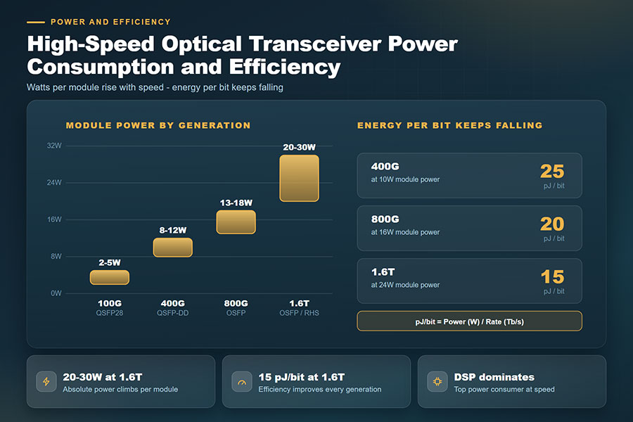
Module power generally increases as aggregate data rates rise. However, the relationship is not strictly proportional. Two transceivers operating at the same data rate can have different power requirements because of differences in optical reach, DSP implementation, laser technology, and form factor.
The following values are indicative planning ranges for common datacom transceiver designs. They are not universal specifications or guaranteed maximum ratings. Always refer to the datasheet of the exact module being deployed.
| Data Rate | Common Form Factor | Indicative Module Power | Typical Applications |
|---|---|---|---|
| 100G | QSFP28 | Approximately 2–5 W | Data center links and network aggregation |
| 400G | QSFP-DD / OSFP / QSFP112 | Approximately 8–12 W | High-density switching and AI networks |
| 800G | QSFP-DD / OSFP | Approximately 13–18 W | AI training clusters and high-capacity data centers |
| 1.6T | OSFP and emerging high-speed form factors | Approximately 20–30 W for many retimed designs | Next-generation AI and cloud networking |
These ranges mainly describe common direct-detection datacom modules. Coherent transceivers designed for longer distances can consume considerably more power. Conversely, certain LPO and LRO implementations can operate below conventional DSP-based module power levels.
3. Why Higher Data Rates Do Not Always Mean Lower Efficiency
Increasing bandwidth requires faster electrical signaling, more capable optical components, and additional signal-processing capacity. As a result, the total power consumed by each module usually increases between generations.
However, aggregate bandwidth can increase faster than module power. This means that a newer transceiver may consume more watts but use less energy to transmit each bit of data.
| Module Generation | Illustrative Power | Nominal Data Rate | Energy per Bit |
|---|---|---|---|
| 400G | 10 W | 400 Gb/s | 25 pJ/bit |
| 800G | 16 W | 800 Gb/s | 20 pJ/bit |
| 1.6T | 24 W | 1,600 Gb/s | 15 pJ/bit |
The figures above are illustrative calculations rather than measurements of specific products. They show how a module can consume more absolute power while improving its energy efficiency per bit.
4. How to Calculate Optical Transceiver Energy Efficiency
Energy per bit is a useful metric for evaluating the power efficiency of optical transceivers. It expresses the amount of energy required to transmit one bit of data.
For example, an 800G optical transceiver consuming 16 W can be evaluated as follows:
A 1.6T module consuming 24 W produces the following result:
Under these assumptions, the 1.6T module consumes more total power but delivers more bandwidth per watt. This is why energy per bit is particularly useful when evaluating different generations of high-speed optical interfaces.
For meaningful comparisons, use consistent measurement boundaries. Module power should be compared with module power, rather than mixing it with figures that include host SerDes, switch ASICs, cooling equipment, or other system components. Actual energy efficiency also depends on usable throughput and operating conditions.
5. DSP-Based Optics, LPO, LRO, and CPO: Different Power Architectures
The location and amount of signal processing have a significant influence on optical interconnect power consumption. Conventional pluggable transceivers, LPO, LRO, and CPO use different approaches to manage electrical signal quality and optical conversion.
DSP-Based Pluggable Optics
Conventional DSP-based modules integrate signal-processing functions inside the transceiver. This provides signal conditioning and supports demanding link requirements, but the DSP and associated circuitry contribute to module power consumption.
Linear Pluggable Optics (LPO)
LPO reduces module-side digital signal processing by using a more linear signal path. It can reduce module power and latency, but places greater demands on host SerDes performance, PCB channel quality, and system-level signal integrity.
Linear Receive Optics (LRO)
LRO reduces or removes selected DSP functions while retaining certain signal-processing capabilities depending on the implementation. Some designs use transmit-side retiming, providing a different balance between power, reach, and signal conditioning.
Co-Packaged Optics (CPO)
CPO places optical engines close to the switch ASIC, shortening high-speed electrical connections. This can reduce electrical interconnect losses, but system-level efficiency must also account for cooling, optical-engine integration, fiber management, and serviceability.
| Architecture | Signal Processing Location | Potential Power Benefit | Key Consideration |
|---|---|---|---|
| DSP-Based | Inside the pluggable module | Established signal-conditioning architecture | DSP power and thermal requirements |
| LPO | More processing handled by host SerDes | Reduced module-side DSP power | Host signal integrity and interoperability |
| LRO | Selected functions removed or reduced | Potential reduction in module processing power | Exact retiming and receiver implementation |
| CPO | Optical engine near the switch ASIC | Potential reduction in electrical interconnect losses | System integration and serviceability |
No architecture is automatically the most efficient for every application. The correct choice depends on transmission distance, host platform capability, signal margin, reliability requirements, and the total power consumed across the complete link.
6. Thermal Management and Power Density in High-Speed Networks
Almost all electrical power consumed by an optical transceiver eventually becomes heat. As module power increases, thermal management becomes more important, especially in switches with high port density.
A switch populated with multiple 800G or 1.6T modules can generate substantial heat around its front-panel cages. Even when each module operates within its own temperature specification, the combined thermal load can challenge the airflow and cooling capacity of the platform.
Calculate Aggregate Optical Module Power
Consider a switch with 32 installed 800G optical modules, each consuming 16 W:
32 × 16 W = 512 W of optical module power.
512 W × 24 hours = 12.288 kWh per day.
12.288 kWh × 365 days = approximately 4,485 kWh per year.
This example covers the optical modules only. It excludes the switch ASIC, fans, power-supply losses, and other system components. Actual energy use depends on operating conditions and module power consumption.
Air Cooling and Liquid Cooling
Air cooling remains widely used for pluggable optical modules. However, higher module power and increasing port density can make airflow design more challenging. Heatsink structure, cage spacing, airflow direction, and fan capacity all influence thermal performance.
Liquid cooling is receiving increasing attention in AI data centers. Depending on the platform design, cold plates or immersion-based solutions can help manage thermal loads that are difficult to address with conventional airflow alone.
C-LIGHT Liquid Immersion Optical Transceiver Solutions
C-LIGHT provides optical transceiver solutions for high-density data center environments, including liquid immersion optical transceivers. These solutions are relevant to deployments where thermal management is an important part of high-speed optical interconnect design.
Module selection should be based on the host platform's mechanical structure, thermal interface, optical specifications, and operating requirements.
7. C-LIGHT High-Speed Optical Transceiver Solutions
High-speed data center networks require optical modules that meet bandwidth, transmission distance, host compatibility, and thermal requirements simultaneously. C-LIGHT offers optical transceiver product families for 400G, 800G, and 1.6T network architectures.
400G QSFP-DD Optical Transceivers
The C-LIGHT 400G QSFP-DD optical transceiver series supports high-capacity data center connectivity. Different optical configurations can be selected according to transmission distance, fiber infrastructure, and network architecture.
Product selection should account for module power limits, optical reach, host compatibility, and the switch platform's thermal design.
800G QSFP-DD Optical Transceivers
The C-LIGHT 800G QSFP-DD optical transceiver series is designed for high-bandwidth data center and AI network applications. The appropriate module configuration depends on the required reach, optical interface, and supported host platform.
At 800G, engineers should evaluate maximum module power and port-level heat generation alongside bandwidth and optical performance.
1.6T OSFP-RHS Optical Transceivers
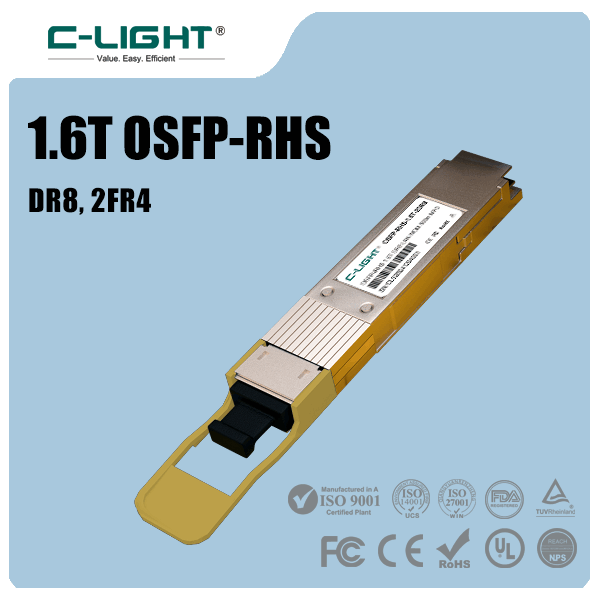
The C-LIGHT 1.6T OSFP-RHS optical transceiver series supports next-generation high-bandwidth connectivity. The product family includes 2×800G configurations, with 500 m and 2 km variants listed for different optical interfaces.
Its reduced-height heatsink design is intended for high-density thermal integration and can be considered in platforms designed around advanced cooling solutions.
8. How to Improve Optical Transceiver Power Efficiency
Reducing optical network power consumption requires more than choosing the module with the lowest wattage. Engineers need to balance electrical power, transmission performance, thermal limits, and network reliability.
Choose the Required Transmission Distance
Select an optical interface that matches the actual link distance and fiber infrastructure. Avoid using a longer-reach or more complex optical architecture when a supported shorter-reach module can meet the link requirements.
Evaluate the Complete Signal Architecture
DSP-based optics, LPO, and LRO have different power and signal-integrity characteristics. Evaluate host SerDes capability, electrical channel loss, FEC requirements, and optical reach before selecting a lower-power architecture.
Optimize Port-Level Power Budgets
Calculate the combined power consumption of all installed modules rather than evaluating each port separately. Use maximum specified module power when planning power supplies and thermal capacity, while using typical operating power for appropriate energy estimates.
Check Platform Compatibility and Cooling
Verify module power-class support, firmware compatibility, airflow direction, operating temperature, and heatsink requirements. A low-power module is not a suitable choice if it cannot meet the host platform's link or compatibility requirements.
Measure Efficiency Using Consistent Conditions
Compare modules using the same data-rate basis, power measurement boundary, and operating conditions. For a complete network assessment, include host SerDes, switch ASIC, optical line equipment, and cooling infrastructure where relevant.
9. Conclusion
High-speed optical transceiver efficiency is becoming an increasingly important consideration in AI data centers and high-capacity Ethernet networks. As interfaces advance from 400G to 800G and 1.6T, absolute module power continues to rise, making electrical provisioning and thermal management more demanding.
At the same time, improvements in DSP technology, optical integration, and signal-processing architectures can reduce energy consumption per transmitted bit. LPO, LRO, and CPO introduce alternative approaches to managing signal processing and electrical interconnect losses, each with different system-level requirements.
Planning a High-Speed Optical Network?
C-LIGHT provides optical transceiver solutions for data centers, AI infrastructure, and high-capacity Ethernet networks. Contact our team for product specifications, compatibility support, and customized optical connectivity requirements.
Contact C-LIGHT >

 >
 >
 >
 >
 >
 >
 >