TEL:+86 132 6656 7067


400G optical transceiver is a high-speed network module designed to transmit and receive up to 400 gigabits per second of data over optical fiber. It converts electrical signals from a switch, router, server, or network interface into optical signals for transmission and converts received optical signals back into electrical signals.
400G optical transceivers are widely used in high-performance data centers, cloud computing networks, AI and machine learning clusters, Ethernet fabrics, and data center interconnects. Depending on the optical architecture, a 400G module can support short-reach multimode links, single-mode links from hundreds of meters to tens of kilometers, or coherent transport for longer data center interconnect applications.
Common 400G solutions include QSFP-DD, QSFP112, and OSFP form factors, with different optical configurations such as 400G-SR8, 400G-DR4, 400G-FR4, 400G-LR4, and 400ZR.
1. What Does a 400G Optical Transceiver Do?
A 400G optical transceiver provides a bidirectional interface between an electrical network port and an optical fiber link. On the transmit side, the module receives high-speed electrical lanes from the host and converts them into optical signals. On the receive side, photodetectors convert incoming optical signals back into electrical signals for the host equipment.
The overall link can be represented as:
Switch / Router / NIC → Electrical Interface → 400G Transceiver → Optical Fiber → 400G Transceiver → Electrical Interface → Switch / Router / NIC
The main difference between 400G optical modules is not simply the data rate. Optical lane count, modulation format, wavelength, fiber type, connector, transmission distance, power consumption, and system architecture all affect the appropriate module selection.
2. How Does a 400G Optical Transceiver Work?
A typical 400G optical transceiver contains an electrical interface, transmitter components, receiver components, optical coupling elements, control electronics, and thermal management structures.
On the transmitting side, the host sends multiple high-speed electrical lanes to the module. The module processes these signals and drives optical transmitters such as VCSELs, EMLs, or other laser technologies depending on the design. The resulting optical signals travel through the fiber.
On the receiving side, photodetectors convert optical signals into electrical signals. The module then performs signal recovery and monitoring before passing the recovered data back to the host system.
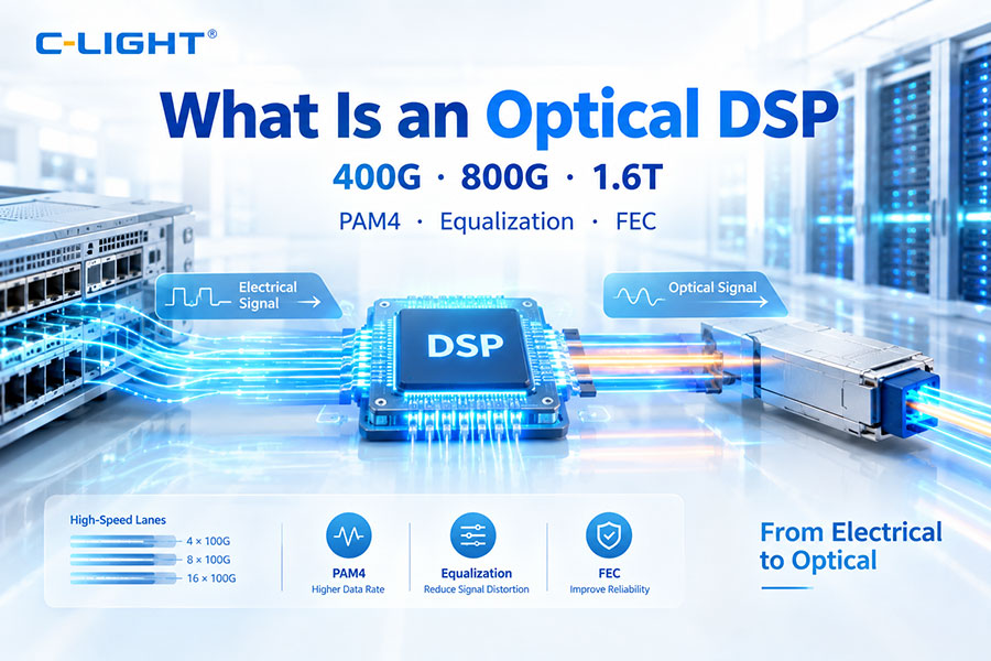
Modern 400G modules commonly use PAM4 signaling and may incorporate DSP, CDR, and FEC-related functions depending on the module and host architecture.
3. Which Form Factors Are Used for 400G?
Several pluggable form factors are used for 400G networking. QSFP-DD and QSFP112 are common in Ethernet and data center environments, while OSFP is also widely used in high-density and AI-oriented systems.
| Form Factor | Typical 400G Architecture | Common Application |
|---|---|---|
| QSFP-DD | 8-lane electrical host interface in many implementations | Data center Ethernet, switches, routers, breakout applications |
| QSFP112 | 4 × 100G electrical lanes | AI/ML fabrics, high-density Ethernet, modern data center switches |
| OSFP | High-density 400G optical and copper connectivity | AI clusters, high-performance switching, high-density networking |
The exact host interface and electrical architecture depend on the module generation and equipment platform. For example, QSFP112 400G modules are built around 100G-per-lane PAM4 signaling, while many earlier 400G implementations use eight 50G-class electrical lanes.
4. Why Does 400G Use PAM4?
PAM4 is a four-level pulse amplitude modulation technology that carries two bits per symbol. This allows more data to be transmitted per symbol than NRZ, which uses two signal levels and carries one bit per symbol.
For 400G networking, PAM4 makes it possible to increase the data rate without requiring an equal increase in the number of physical lanes. A typical 400G implementation may use four 100G-class lanes or eight 50G-class lanes depending on the architecture.
| Parameter | NRZ | PAM4 |
|---|---|---|
| Signal Levels | 2 | 4 |
| Bits per Symbol | 1 | 2 |
| Data Rate Efficiency | Lower | Higher |
| Use in Modern 400G | Limited | Common |
PAM4 also introduces tighter signal margins and greater sensitivity to loss, noise, crosstalk, and distortion. This is one reason why high-speed 400G systems depend heavily on advanced electrical design, equalization, DSP, and FEC.
5. What Are the Main Types of 400G Optical Transceivers?
| Type | Wavelength | Fiber | Typical Reach | Typical Connector |
|---|---|---|---|---|
| 400G-SR8 | 850 nm | MMF | Up to 100 m on OM4 | MPO-16 |
| 400G-DR4 | 1310 nm region | SMF | 500 m | MPO-12 |
| 400G-FR4 | 1271/1291/1311/1331 nm | SMF | 2 km | Duplex LC |
| 400G-LR4 | 1271/1291/1311/1331 nm | SMF | 10 km | Duplex LC |
| 400G-LR8 | 1310 nm region with multiple wavelengths | SMF | 10 km | Duplex LC |
| 400ZR | 1550 nm C-band | SMF | Typically up to 120 km single span | Duplex LC or other module-dependent interface |
These categories cover very different network environments. SR8 is optimized for short in-building data center links, DR4 for several hundred meters of single-mode fiber, FR4 for approximately 2 km, LR4 for approximately 10 km, and 400ZR for coherent data center interconnect applications.
6. What Is a 400G-SR8 Optical Transceiver?
400G-SR8 is a short-reach 400G multimode optical architecture. It typically operates around 850 nm and uses eight optical lanes, making it suitable for high-density links inside data centers.
A common 400G-SR8 implementation uses an MPO-16 connector and OM4 multimode fiber. Typical reach is up to 100 meters on OM4, making it suitable for connections between servers, switches, and nearby network cabinets.
SR8 is particularly relevant where existing multimode infrastructure and short fiber distances are important. Breakout configurations can also allow a 400G port to connect to lower-speed interfaces depending on the host and module design.
7. What Is a 400G-DR4 Optical Transceiver?
400G-DR4 is a parallel single-mode optical architecture designed for approximately 500 meters of reach. It commonly operates around 1310 nm and uses four optical lanes over parallel single-mode fiber.
A typical DR4 module uses an MPO-12 connector. Each optical lane carries approximately 100G-class signaling, allowing four lanes to provide the aggregate 400G data rate.
400G-DR4 is widely suited to data center leaf-spine connections, AI cluster networks, and switch-to-switch links where single-mode fiber is preferred and the reach is longer than conventional multimode solutions.
8. What Is a 400G-FR4 Optical Transceiver?
400G-FR4 is a two-kilometer-class single-mode optical transceiver. It typically uses four CWDM wavelengths around 1271 nm, 1291 nm, 1311 nm, and 1331 nm and combines the channels onto a duplex single-mode fiber link.
Unlike parallel-fiber DR4, FR4 uses wavelength multiplexing to transmit four optical channels over two fibers. A duplex LC connector is therefore commonly used.
FR4 is useful for data center networks where the link distance is beyond typical DR4 deployment requirements but does not require a 10 km LR4 link.
9. What Is a 400G-LR4 Optical Transceiver?
400G-LR4 is a 10-kilometer-class single-mode optical transceiver commonly used for longer data center links. It uses four optical wavelengths in the 1310 nm region and combines the channels through wavelength multiplexing.
A typical LR4 module uses a duplex LC connector and four optical channels. Compared with FR4, LR4 is designed for longer reach and therefore typically requires greater optical performance and link budget.
400G-LR4 can be used for large campus data centers, longer leaf-spine connections, enterprise data center interconnection, and other 10 km-class Ethernet applications.
10. What Is a 400G-LR8 or 400G-ER4?
400G-LR8 is another 10 km-class architecture that uses multiple optical wavelengths to support 400G transmission over single-mode fiber. Compared with four-lane architectures such as LR4, LR8 uses more optical channels and a different wavelength arrangement.
400G-ER4 is intended for extended-reach applications beyond conventional 10 km links. The exact transmission distance, optical budget, transmitter technology, receiver sensitivity, and FEC requirements depend on the specific implementation.
Extended-reach 400G solutions are generally selected when the fiber route exceeds the design range of conventional DR4, FR4, or LR4 modules.
11. What Is 400ZR?
400ZR is a coherent 400G optical technology developed primarily for high-capacity data center interconnect applications. It is different from short- and medium-reach direct-detection Ethernet optics such as SR8, DR4, FR4, and LR4.
400ZR uses coherent transmission and advanced digital signal processing to transport 400GbE over single-mode fiber. The OIF 400ZR implementation agreement targets router-to-router interconnection over single-span links up to approximately 120 km, including amplified or DWDM-based configurations.
Because 400ZR is designed for DCI rather than conventional in-rack or short data center switching, it operates in a different optical and network architecture category from standard 400G client optics.
12. What Fiber Types Are Used with 400G?
400G transceivers can use either multimode fiber or single-mode fiber depending on the transmission distance and optical architecture.
| Fiber Type | Typical 400G Application | Typical Reach Class |
|---|---|---|
| OM3 / OM4 / OM5 MMF | SR and VR short-reach links | Tens of meters to approximately 100 m |
| OS2 / G.652 SMF | DR4, FR4, LR4 and other single-mode links | Hundreds of meters to 10 km or more |
| G.652 SMF with coherent optics | 400ZR and DCI | Metro / DCI distances |
The fiber type must match the transceiver specification. Using the wrong fiber category can significantly reduce the supported distance or prevent the link from operating correctly.
13. How Much Power Does a 400G Optical Transceiver Use?
Power consumption depends strongly on the form factor, optical architecture, lane rate, DSP design, laser technology, temperature range, and host interface.
For example, recent 400G QSFP112 modules can have maximum power ratings around 9 W, while specific QSFP-DD products vary by optical architecture and generation. Short-reach, parallel, CWDM, and coherent modules can all have different power requirements.
Power is particularly important in high-density AI and cloud data centers because hundreds or thousands of optical modules may operate within the same switching system. Module power therefore affects rack-level power consumption, thermal design, and cooling requirements.
14. What Is the Optical Power Budget of a 400G Transceiver?
The optical power budget indicates how much optical loss the link can tolerate while maintaining the required receiver performance.
A simplified calculation is:
Optical Power Budget = Transmitter Output Power − Receiver Sensitivity
For example, if a transmitter provides 3 dBm and the receiver sensitivity is -5 dBm, the theoretical power budget is approximately 8 dB.
Actual link planning must also account for connector loss, splice loss, fiber attenuation, patch panels, bends, cassettes, and other passive components. The total channel loss must remain within the module's specified operating limits.
15. Do 400G Optical Transceivers Need DSP and FEC?
Modern 400G architectures commonly rely on advanced electrical and optical signal processing. DSP can perform functions such as equalization, signal recovery, lane processing, monitoring, and other high-speed signal functions.
FEC provides additional error correction capability and is particularly important for maintaining reliable high-speed transmission when signal margins are limited.
However, the exact division of DSP and FEC functions between the transceiver and host platform depends on the architecture. Some 400G modules perform significant processing within the module, while standards and system implementations may place FEC functions in the host device.
16. Can a 400G Optical Transceiver Support Breakout?
Yes. Many 400G modules support breakout architectures that divide a single 400G connection into multiple lower-speed links.
For example, a 400G port can be designed to operate as four 100G connections or, depending on the electrical and optical architecture, other combinations supported by the switch and transceiver.
| 400G Architecture | Possible Breakout Example | Typical Use |
|---|---|---|
| 400G-DR4 | 4 × 100G | Leaf-spine and AI fabric connectivity |
| 400G-SR8 | Multiple lower-speed links depending on platform | Short-reach data center switching |
| 400G QSFP112 | 4 × 100G or other supported modes | High-density Ethernet and AI networks |
Breakout must be supported by both the transceiver and the host switch or NIC. The optical connector and lane mapping also need to match the breakout cable and the destination interface.
17. Where Are 400G Optical Transceivers Used?
400G optical transceivers are used in several high-bandwidth networking environments.
AI and Machine Learning Clusters: AI workloads generate large amounts of East-West traffic between GPUs, switches, storage systems, and other compute resources. 400G connectivity is widely used in high-performance AI Ethernet and related data center fabrics.
Cloud Data Centers: Hyperscale and cloud networks use 400G links to increase switch capacity while reducing the number of physical interfaces required for a given aggregate bandwidth.
Enterprise Data Centers: 400G can be deployed in high-capacity spine, aggregation, storage, and inter-building connections.
Data Center Interconnect: Longer-reach 400G solutions, including coherent 400ZR, can connect geographically separated data center sites.
High-Performance Computing: HPC environments require high throughput and low-latency networking between compute nodes and storage systems, making 400G an important interconnect rate.
18. How Should You Choose a 400G Optical Transceiver?
The correct module should be selected according to the actual network link rather than the 400G data rate alone.
| Requirement | Typical Choice |
|---|---|
| Very short reach, multimode infrastructure | 400G-SR8 / VR-class solution |
| Up to about 500 m over SMF | 400G-DR4 |
| Up to about 2 km over SMF | 400G-FR4 |
| Up to about 10 km over SMF | 400G-LR4 / LR8 |
| Metro / DCI connectivity | 400ZR or another coherent 400G solution |
Other important selection factors include switch compatibility, QSFP-DD/QSFP112/OSFP support, optical connector type, fiber type, operating temperature, maximum power, FEC requirements, breakout capability, and the available optical link budget.
19. How Does 400G Fit into the Evolution Toward 800G and 1.6T?
400G has become an important transition point between earlier 100G and 200G networking and newer 800G and 1.6T systems.
As network traffic increases, higher per-lane speeds reduce the number of lanes required for a given aggregate bandwidth. For example, 400G can be implemented using four 100G-class lanes, while newer 800G and 1.6T solutions increasingly use 200G-per-lane and 400G-per-lane architectures.
This evolution is especially significant in AI data centers, where switch capacity, optical density, power consumption, thermal management, and port scalability must be considered together.
C-LIGHT supports a range of 400G connectivity solutions, including 400G QSFP-DD, QSFP112, and OSFP optical and copper interconnect products, allowing network designers to select optical transceivers, DACs, AECs, and other connectivity options according to link distance and system architecture.
20. Conclusion
A 400G optical transceiver is a high-speed optical networking module designed to provide up to 400Gb/s aggregate connectivity between switches, routers, servers, NICs, and other network equipment.
The 400G ecosystem includes short-reach multimode solutions such as SR8, single-mode parallel optics such as DR4, wavelength-multiplexed architectures such as FR4 and LR4, and coherent solutions such as 400ZR for data center interconnects.
Choosing the right 400G transceiver requires more than matching the network speed. Fiber type, transmission distance, optical connector, lane architecture, wavelength, power consumption, optical budget, FEC, breakout support, and equipment compatibility should all be evaluated before deployment.
 >
>

 >
>
 >
>
 >
>
 >
>
 >
>
 >
>
 >
>