TEL:+86 132 6656 7067


OTU4 is a high-capacity optical transport signal defined by ITU-T G.709 for 100G-class optical networking. With a nominal line rate of approximately 111.81 Gbit/s, it provides the framing, transport overhead and forward error correction capacity required to carry high-speed client signals through optical transport infrastructure.
OTU4-compatible optical interfaces are used in DWDM systems, metro transport networks, long-haul backbones and data center interconnects. Depending on the implementation, an OTU4 transceiver may provide a short-reach 100G optical interface or a tunable coherent wavelength for longer-distance transmission.
1. What Is an OTU4 Optical Transceiver?
An OTU4 optical transceiver is a pluggable optical module or optical interface designed to transmit and receive signals associated with the OTU4 transport format. OTU4 stands for Optical Transport Unit level 4 and belongs to the OTN hierarchy specified by ITU-T G.709.
Unlike a conventional 100G Ethernet optical module that is designed primarily around an Ethernet PHY interface, an OTU4 interface operates within the OTN transport framework. It can carry client traffic such as 100 Gigabit Ethernet while providing transport-layer functions including framing, error monitoring and FEC.
The term OTU4 optical transceiver does not identify one specific hardware design. Products may use different form factors, optical technologies, wavelengths, modulation formats and transmission distances. Some support direct OTU4 client interfaces, while others generate an OTU4 line signal through an integrated transponder or coherent optical architecture.
| Parameter | OTU4 Characteristics |
|---|---|
| Standard | ITU-T G.709 / Y.1331 |
| Transport level | Optical Transport Unit 4 |
| Nominal line bit rate | Approximately 111.81 Gbit/s |
| Typical client capacity | 100G-class client signals, including 100GbE |
| Transport structure | OTU4 / ODU4 / OPU4 |
| FEC | Defined by the applicable G.709 implementation and interface profile |
| Common applications | DWDM, metro transport, backbone networks and DCI |
The 111.81 Gbit/s figure is the nominal OTU4 signal rate, not the user payload throughput. The additional capacity accommodates OTN framing, overhead and FEC information.
2. OTU4 Line Rate and Its Relationship with 100G Ethernet
One of the most important OTU4 specifications is its nominal line rate of approximately 111.81 Gbit/s. This rate is higher than the nominal 100G service designation because the transport signal must carry more than the client payload alone.
A typical 100GbE signal uses an aggregate physical-layer rate of approximately 103.125 Gbit/s after 64b/66b encoding. When adapted into an OTN structure, the client signal is carried within an OPU4 payload and an ODU4 path container. The resulting OTU4 signal includes additional transport overhead and FEC capacity.
| Signal | Approximate Bit Rate | Function |
|---|---|---|
| 100GbE client signal | 103.125 Gbit/s | Ethernet client interface after physical coding |
| OPU4 payload structure | Based on the ODU4/OPU4 transport hierarchy | Adapts client traffic into the OTN payload area |
| OTU4 line signal | 111.809973568 Gbit/s | Transports the OTN frame with overhead and FEC |
The difference between the Ethernet client rate and the OTU4 line rate should not be interpreted as unused Ethernet bandwidth. It is part of the transport structure that allows the optical network to manage and monitor the carried service.
A 100G Ethernet optical module is not automatically an OTU4 transceiver. The module, host interface and equipment must explicitly support the required OTU4 signal format or mapping function. Compatibility depends on the complete interface specification, not just the advertised 100G data rate.
3. How OTU4 Framing Works: OPU4, ODU4 and OTU4
OTU4 transmission uses a layered frame structure. The three principal components are OPU4, ODU4 and OTU4. Each performs a different function in the transport process.
OTU4 Transport Frame Structure
OPU4 (Optical Payload Unit): Provides the payload area and client-signal adaptation functions. It accommodates the mapped client signal within the OTN frame.
ODU4 (Optical Data Unit): Provides the path-layer transport structure. It carries path overhead and supports performance monitoring and transport management.
OTU4 (Optical Transport Unit): Adds the transport-section overhead and FEC information required for transmission across the optical transport section.
At the transmitting end, the client signal is mapped into the OPU4 structure. The ODU4 and OTU4 layers add their respective overhead information, and the completed signal is sent through the optical interface.
At the receiving end, the transport signal is recovered, checked and processed through the corresponding OTN layers. The client payload is then extracted and delivered to the destination interface.
This layered structure enables network operators to monitor transport performance independently of the client service carried inside the OTN container.
4. OTU4 FEC and Transport Performance Monitoring
Forward Error Correction is a key feature of OTU4 transport. Optical transmission over long fiber routes can introduce signal degradation through attenuation, noise, dispersion and other impairments. FEC adds redundant information to the transmitted signal so that the receiver can detect and correct a defined range of errors.
OTU4 implementations use the FEC scheme specified for the relevant G.709 interface or equipment profile. The exact coding method and performance depend on the implementation. Different optical interfaces may also support additional proprietary or standardized enhanced-FEC options.
OTU4 overhead provides monitoring information that helps network equipment evaluate transmission quality and identify faults. Relevant operational measurements may include:
Bit error performance and FEC correction statistics.
Loss of signal and loss of frame conditions.
Transport alarm indications and defect reporting.
Path-level performance monitoring.
Optical receive power and transmitter operating status where module diagnostics are available.
FEC statistics are especially useful when an optical link remains operational but its error-correction workload increases. A rising corrected-error count can indicate declining optical margin before the link experiences an uncorrectable error condition.
For practical troubleshooting, engineers should evaluate optical power, OSNR where applicable, pre-FEC and post-FEC error performance, fiber quality and the configured FEC profile together. A single receive-power measurement cannot establish the complete health of an OTU4 link.
5. Common OTU4 Optical Transceiver Types
OTU4-capable optical interfaces are available in different hardware and optical architectures. Selection depends on the network equipment, required distance, wavelength plan and whether the interface is used for client access or optical line transmission.
| Interface Type | Optical Technology | Typical Application |
|---|---|---|
| 100G LAN-WDM | Multiple closely spaced wavelengths, commonly using four optical lanes | 100G client and OTN interfaces over specified short or metro reaches |
| 100G Coherent DWDM | Coherent modulation and digital signal processing | Tunable wavelength transmission over DWDM infrastructure |
| 100G Transponder Interface | Client-to-line signal conversion and OTN mapping | Converting 100GbE client traffic into an OTU4 optical line signal |
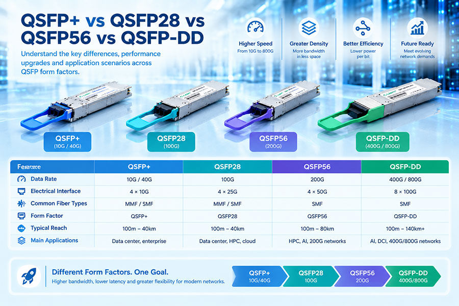
| OTU4-Compatible CFP2 / QSFP28 Interfaces | Depends on the product implementation | Compact optical transport equipment and compatible host platforms |
For example, a 100G LAN-WDM module may use four optical wavelengths around the 28G-per-lane range and combine them into a 100G-class optical interface. A coherent DWDM module uses a different transmission architecture, typically with a tunable C-band laser, coherent receiver and DSP.
These technologies should not be treated as interchangeable. A LAN-WDM module designed for a specified client interface does not automatically provide the tunability or long-distance performance of a coherent DWDM module.
6. Where Are OTU4 Optical Transceivers Used?
OTU4 interfaces are primarily deployed in networks that require 100G-class transport with structured optical-layer management. Their applications extend from metro aggregation to long-distance backbone transmission.
Metro Optical Transport Networks
Metro networks aggregate traffic from enterprise access sites, mobile transport infrastructure, data centers and regional network nodes. OTU4 can transport 100G-class services between metro locations while providing path monitoring and standardized transport framing.
DWDM Systems
DWDM systems carry multiple optical wavelengths over a shared fiber pair. An OTU4 signal can serve as a 100G-class wavelength payload or transport interface, depending on the transponder and line-system architecture. Coherent DWDM implementations are particularly useful when longer reach, tunable wavelengths and higher spectral efficiency are required.
Carrier Backbone Networks
Telecommunications operators use high-capacity optical transport to connect major switching centers, regional hubs and core network locations. OTU4 supports the transport of 100G services through managed optical paths, with monitoring and FEC functions suited to carrier environments.
Data Center Interconnect (DCI)
Large data centers exchange storage traffic, application data, replication traffic and cloud services across geographically separated facilities. OTU4-capable interfaces can be used in 100G transport architectures, including systems that connect client-facing Ethernet equipment to DWDM line infrastructure.
Enterprise and Wholesale Optical Services
Network providers may use OTN transport to deliver managed bandwidth between customer sites. OTU4 provides a transport framework for 100G-class services where path-level monitoring, service isolation and optical infrastructure management are important.
7. OTU4 in a DWDM Optical Transport Architecture
OTU4 and DWDM perform complementary functions. OTU4 defines the digital transport signal structure, while DWDM combines multiple optical wavelengths onto a fiber infrastructure. A transponder or compatible optical interface connects the digital transport layer to the optical line system.
Example 100G OTU4 over DWDM Architecture
In a transponder-based system, the client-facing interface receives the 100GbE signal and adapts it into an OTU4 line signal. The line interface then transmits the signal over the assigned DWDM wavelength.
Some modern coherent pluggable modules integrate more of the optical transmission functionality into a compact form factor. Depending on the product, they may support 100G Ethernet and OTU4 client or line-side operation. The exact mapping, host interface and FEC support must be verified against the module datasheet.
C-LIGHT DWDM DCO Coherent Optical Transceivers
C-LIGHT offers DWDM DCO transceiver options across 100G to 800G product categories, with form factors including QSFP28, CFP2, QSFP-DD and OSFP. These products are relevant to coherent optical transport, tunable C-band wavelength applications and DCI infrastructure.
For an OTU4 deployment, verify the specific module's supported client format, OTL interface, line-side protocol, FEC mode and host equipment compatibility. A 100G coherent DCO module should not be assumed to support OTU4 solely because it operates at a 100G-class rate.
8. OTU4 vs. 100G Ethernet Optical Transceivers
OTU4 and 100G Ethernet are closely related because OTN can transport 100GbE client signals. However, their interfaces and operational purposes are different.
| Comparison | 100G Ethernet Optical Interface | OTU4 Optical Interface |
|---|---|---|
| Primary standard | IEEE 802.3 | ITU-T G.709 |
| Primary function | Ethernet frame transmission | OTN transport signal transmission |
| Nominal signal rate | Depends on the Ethernet PHY; 100GBASE-R uses approximately 103.125 Gbit/s at the encoded interface | Approximately 111.81 Gbit/s |
| Transport overhead | Ethernet PHY and MAC-related encoding and control structures | OTN overhead and FEC within the transport frame |
| Monitoring | Ethernet link and service monitoring | OTN transport and path monitoring |
| Typical network role | Client connectivity and packet switching | Optical transport and service aggregation |
| Compatibility | Requires matching Ethernet PHY and host interface | Requires matching OTU4/OTL interface and supported OTN configuration |
A dual-rate or multi-protocol optical module may support both 100G Ethernet and OTU4 operation. However, this capability must be explicitly stated in its datasheet. The host platform must also support the required electrical interface, signal rate and management configuration.
9. Key Parameters When Selecting an OTU4 Transceiver
Choosing an OTU4 optical interface requires more than matching the 100G rate. The optical module must be compatible with the transport equipment and the intended optical link.
Client and line protocol: Confirm whether the module supports 100GbE, OTU4 client signals, OTU4 line signals or multiple operating modes.
Host electrical interface: Check OTL4.4, OTL4.10 or the relevant electrical interface supported by the equipment.
Optical reach: Select the appropriate interface for the fiber distance, link loss, optical budget and network design.
Wavelength: Confirm whether the module uses fixed LAN-WDM wavelengths or a tunable DWDM C-band wavelength.
FEC compatibility: Verify the supported FEC scheme and ensure that the transmitting and receiving equipment use compatible settings.
Optical performance: Review transmit power, receiver sensitivity, OSNR requirements where applicable, dispersion tolerance and link margin.
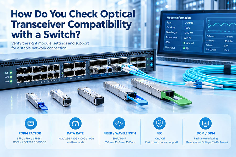
Form factor: Check whether the host equipment supports CFP2, QSFP28 or another specified module format.
Management and diagnostics: Confirm support for DDM/DOM, I2C or the applicable management interface.
Environmental conditions: Check operating temperature, power consumption and cooling requirements.
OTU4 is a standardized signal format, but that does not guarantee universal interoperability between all OTU4-labelled modules and platforms. Host electrical interfaces, optical application codes, FEC profiles, management firmware and vendor qualification can all affect compatibility.
10. Common OTU4 Link Problems and Troubleshooting
OTU4 link faults may originate in the client interface, OTN processing, optical module or fiber infrastructure. A structured diagnostic process helps isolate the failing layer.
| Observed Condition | Possible Cause | Recommended Check |
|---|---|---|
| Loss of signal | Fiber disconnection, incorrect patching or transmitter failure | Inspect fiber connections, optical output and remote transmitter status |
| OTU4 framing alarm | Incorrect signal format or incompatible interface configuration | Verify OTU4 framing, OTL interface and equipment operating mode |
| High corrected FEC count | Reduced optical margin, noise or transmission impairments | Check pre-FEC performance, OSNR where relevant and optical link quality |
| Uncorrectable errors | Signal degradation beyond the FEC correction capability | Inspect fiber loss, connectors, optical power and FEC compatibility |
| Intermittent link instability | Temperature variation, unstable optical power or equipment issues | Review module diagnostics, environmental conditions and alarm history |
| Client service unavailable | Client mapping, port configuration or OTN cross-connect issue | Verify client mapping, ODU configuration and transport path provisioning |
Optical power should always be assessed against the specified transmitter and receiver limits. For coherent DWDM links, OSNR, chromatic dispersion, polarization effects and the configured modulation and FEC modes may also be relevant. Replacing an optical module without checking the complete transport configuration can leave the underlying problem unresolved.
11. OTU4's Role in the Evolution of High-Capacity Optical Networks
OTU4 remains relevant in installed 100G transport infrastructure, particularly in metro, regional and backbone networks. As network traffic grows, operators are also deploying higher-capacity OTN interfaces and coherent optical technologies to increase fiber utilization and reduce the number of required transport wavelengths.
Newer transport architectures support rates beyond OTU4, including OTUCn structures and higher-capacity coherent optical interfaces. These technologies address growing requirements from cloud infrastructure, AI data centers, hyperscale connectivity and high-bandwidth interconnection services.
In many networks, OTU4 continues to serve as an established 100G transport layer alongside newer 400G and 800G optical systems. The migration path depends on existing line systems, equipment lifecycle, service requirements and the cost of upgrading optical infrastructure.
12. Conclusion
An OTU4 optical transceiver provides an interface for 100G-class optical transport based on the ITU-T G.709 framework. Its approximately 111.81 Gbit/s line rate accommodates the client payload together with OTN overhead and FEC information.
OTU4 is widely associated with DWDM transport, metro networks, carrier backbones and 100G data center interconnects. Its value lies not simply in optical bandwidth, but in the structured framing, performance monitoring and transport capabilities of OTN.
When selecting an OTU4-compatible module, network engineers should verify the client protocol, electrical interface, optical reach, wavelength, FEC mode and host compatibility. These parameters determine whether the module can operate correctly within the intended optical transport architecture.
Looking for 100G and high-capacity DWDM optical connectivity?
C-LIGHT provides optical transceivers and coherent DCO solutions for data center interconnect, metro transport and optical backbone applications.
Contact C-LIGHT for product specifications, compatibility support and optical transport requirements.
 >

 >
 >
 >
 >
 >
 >
 >