 TEL:+86 158 1857 3751


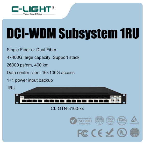
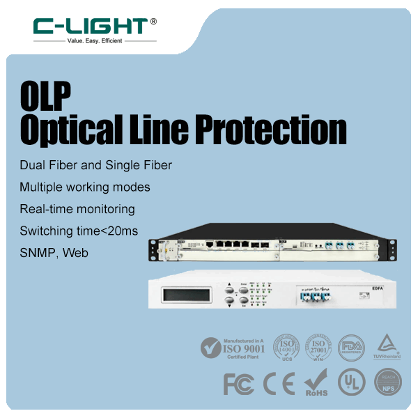
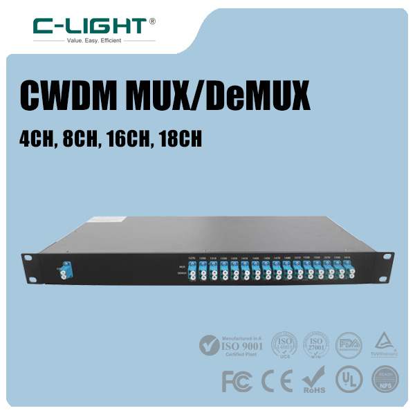
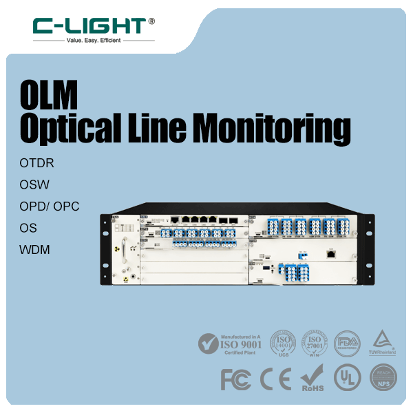


Application


Support&Service


News


Any question?
We are here ready for you.
We are here ready for you.

Get expert advice quickly,Meet your requirements in all aspects.
Phone : +86 158 1857 3751
Email : sales@c-light.com

Phone:+86 158 1857 3751
E-mail:sales@c-light.com
E-mail:sales@c-light.com
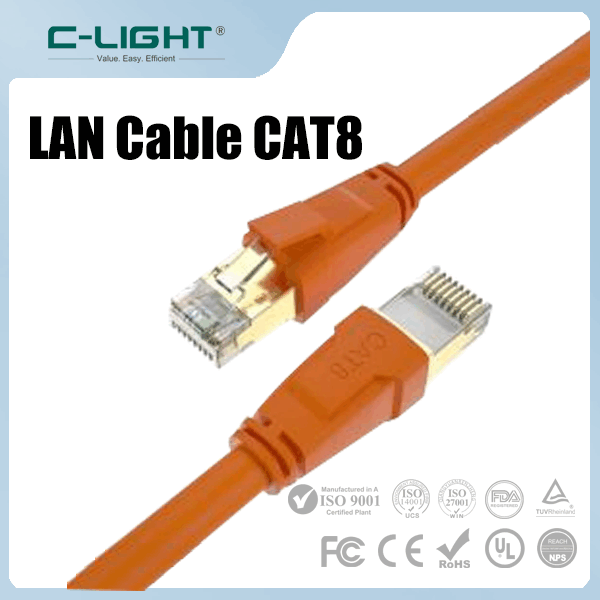
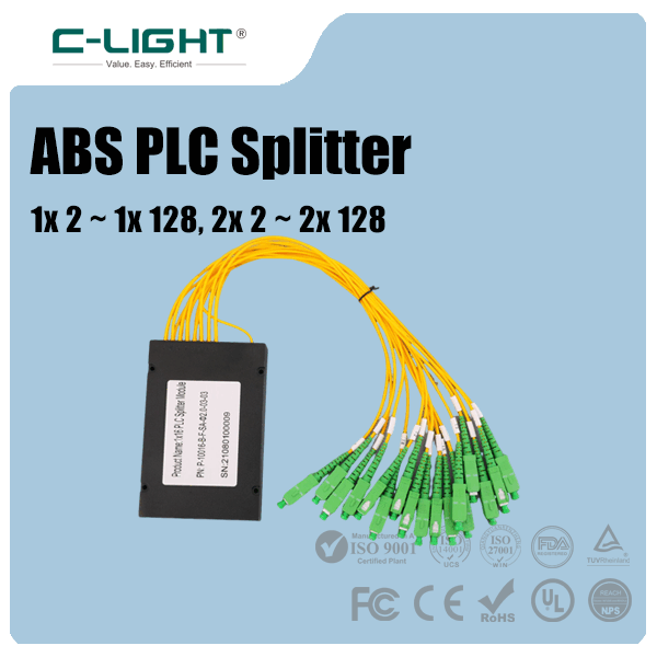
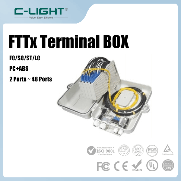
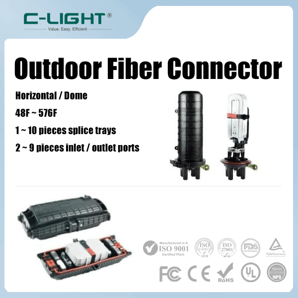
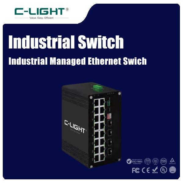
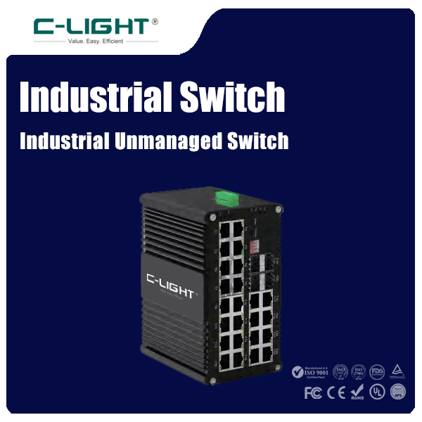
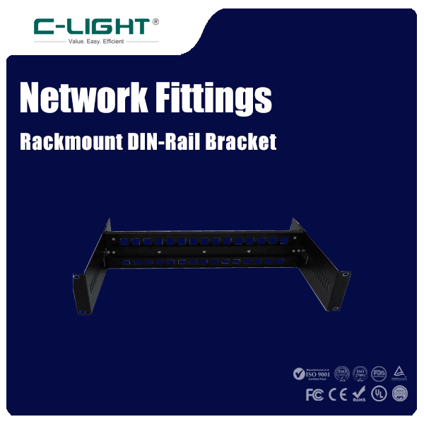
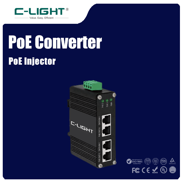
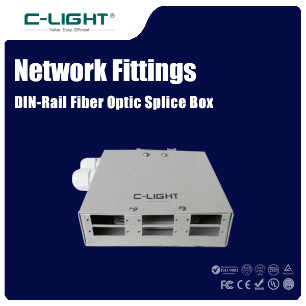
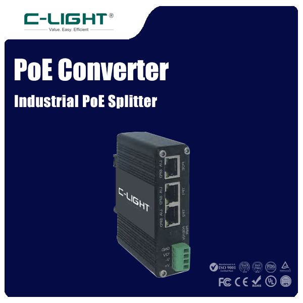
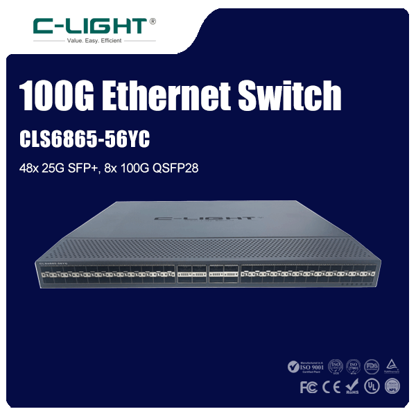
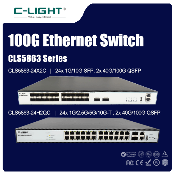
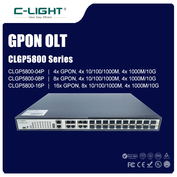
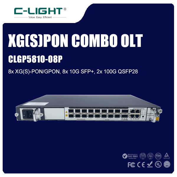
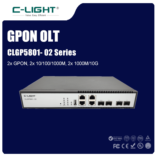
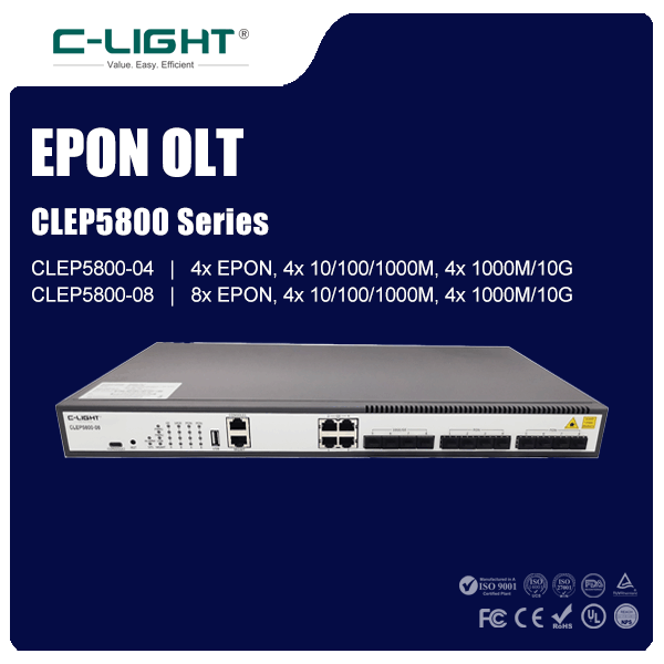
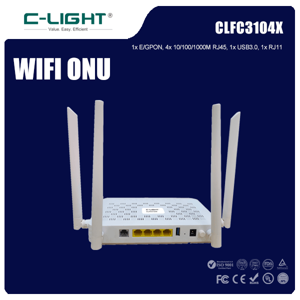
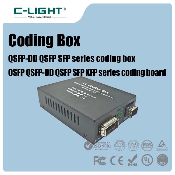
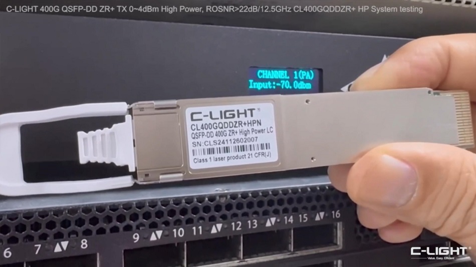
Popular Products
Copyright © 2011-2025 C-LIGHT.COM INC.
All Rights Reserved
All Rights Reserved
-
- Call