In the process of upgrading optical modules, in order to pursue higher transmission rates, multi-channel parallel mode has been developed to provide support for higher transmission bandwidth. The IEEE 802.3ba standard defines 40G and 100G Ethernet protocols, both implemented as parallel channels.
For multi-channel parallel modules, the most efficient test method is of course parallel testing, this section will take 100G QSFP28 optical module as an example for everyone to uncover a variety of 100G optical module test schemes, and then a brief introduction to the test instruments used in the parallel test scheme.
Virtual instrument technology is the main means used by most optical module manufacturers to design optical module automatic test system.
The test system integrates advanced test equipment at home and abroad: optical oscilloscope, error meter, optical power meter, optical attenuator and so on.
Through the GPIB bus or other channels to connect to the PC side, the PC side based on the virtual instrument computer software system control, to achieve real-time control of each measuring instrument, complete the module automatic test process.
The test system scheme generally debuts and measures the transmitting end and the receiving end of the module separately. After the initial test and aging, the final test is carried out uniformly.
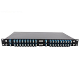
Test the Tx of 100G optical module

100G QSFP28 optical module transmitter test block diagram
The performance index of optical transceiver can be characterized by optical eye map information
As shown in the figure, the optical module to be combined with the test board converts the high-speed electrical signal provided by the bit error meter into an optical signal and connects it to the optical oscilloscope through the optical fiber jumper. At the same time, the Trigger end of the bit error meter connects the synchronous clock signal to the oscilloscope to realize signal synchronization and form an eye map on the optical oscilloscope.
The optical oscilloscope needs to select the filter rate and center wavelength corresponding to the optical module to be measured, select the appropriate eye pattern template to match the formed eye pattern, and the test system sends the generated eye pattern information (transmitted light power, extinction ratio, eye pattern rising and falling time, eye pattern crossing point, etc.) to the upper bit computer through the GBIP bus.
During the test, the appropriate optical power and extinction ratio should be set according to the target requirements of the module index, and the transmitted optical power value of the digital diagnosis of the module should be calibrated with the actual value, and the Ibias should be adjusted to make the optical power within the qualified range. The host computer will write the debuggable data value into the EEPROM of the module through the test board.
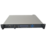
100G optical transceiver Rx test

100G QSFP28 optical transceiver Rx test block diagram
The sensitivity test is performed on the Rx of the optical module
Generally, a standard optical module is selected as the standard optical emission source, and the high-speed electrical signal generated by the error meter is driven by the test board to generate the standard signal source.
The sensitivity test requires a programmable optical attenuator to attenuate the power of the signal, so that the optical module receiver receives signals of different power. Finally, the sensitivity test is completed by comparing the bit error rate under different optical power with the error meter.
During the test, the alarm value is set first, and the received optical power DMM value of the module is calibrated. The programmable optical attenuator is adjusted to detect the optical power value at the receiving end of the module with a specific bit error rate (BRT=10-12), that is, the sensitivity index.
In the actual test process, the bit error rate under certain optical power conditions is generally obtained by adjusting the optical attenuator, and then the module sensitivity is estimated by curve fitting and other methods. Compare the alarm threshold and check whether Los Assert and Los Dessert reach the preset threshold.
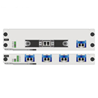
100G optical module Final test

100G QSFP28 optical module overall test block diagram
Optical module manufacturers generally age the optical modules tested at the transmitting and receiving ends respectively and then test the module parameters again to determine the changes in functional parameters caused by aging of the optical modules.
In the test scheme as shown in the above figure, the sensitivity and eye image optical indexes can be measured at the same time. In the actual test, two error detectors may be required to drive two test boards respectively. In order to drive two test boards respectively with two differential outputs of one error meter, high-quality code generator (PPG) should be selected.
Other test schemes
Module manufacturers can build different test systems according to different optical modules and actual equipment conditions. The following describes the structure of the two test schemes

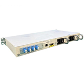
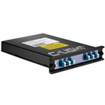
system scheme with optical error test
The test system scheme in the above figure adopts a bit error meter with a standard light source, and uses a combination of a multi-channel splitter and an attenuator to complete the receiver calibration, positive and negative alarm test and sensitivity test.
The optical power at the receiving end of the module is measured by a 1X2 splitter and an optical power meter.
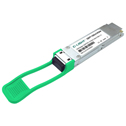
C-light High-speed transceivers
Cost-effective
R&D has excellent capability in selecting solutions.
Excellent supply chain support for procurement
Production has strict and controllable quality assurance capabilities.
Products will be shipped after 100% data center system equipment validation.
Continuous Upgrade
Sustainable cost reduction and upgrade of hardware and software
Universality upgrades with product application environment requirements.
400G/800G R&D.
Flexible production capacity according to demand.
Customized Service
Optical chip and driver chip solution.
Transmit power range.
Receiving sensitivity range.
Product appearance and packaging.


 Your current position: