The key technology of optical module hot plug is to use the following technologies and methods to realize the hot plug of optical communication module.
(1) In order to ensure the safety of the laser in the hot plug process, the following two technologies are used.
① Power on delay self check. TX fault signal is used to ensure that only when the circuit is normal, the driving IC provides bias and modulation current to the laser, and the laser works; when the circuit is abnormal, the driving IC does not provide current, there is no current on the laser, and the laser will not be damaged. The MSA multi-source protocol defines a TX fault signal to indicate whether the operation of the optical module is normal. There is an initialization sequence when the optical module is inserted. After power on, the optical module first "self check". If the "self check" passes, drive the IC to provide current to the laser, and then the laser can start to work. After the optical module is powered on, after the time delay of T init time, during this period, TX fault is high level, driving IC does not provide current, and laser does not work. If there is a TX disable command in the initial power on system, the T init time will start counting after the TX disable becomes low. If there is no abnormality after the T init delay, the TX fault will turn to low level, and the driving IC will provide current, so the laser can work normally. If the TX fault remains high after the T init delay, the module fault will be judged. The driving IC will not provide current, and the laser will not work, The TX fault is displayed to ensure that the laser will not be damaged when the circuit is abnormal. Refer to figure 1 and Figure 2 for the initialization sequence of hot plug when tx_disable is high and low at the beginning of power on.

Figure 1
Figure 2
② Turn off LD in case of failure. In addition to power on self-test, the design of the circuit also adds a turn off circuit to ensure the safety of the laser hardware. Generally, the driver IC has a shutdown pin. When designing the shutdown circuit, the shutdown pin connects the gate of the FET and controls the on-off of the FET. In normal condition, shutdown outputs low level, FET is on, there is current flowing on the laser, and the laser lights normally; in abnormal condition, shutdown outputs high level, FET is off, and there is no current flowing on the laser, which ensures its safety in hardware. Turn off the circuit as shown in Figure 3.
Figure 3
(2) By using a specific power on sequence and adding filter circuit Method to reduce the surge circuit.
① Adopt specific power on sequence to reduce surge through pre impulse Electric current. In order to prevent the components from being damaged, there is a power on / off sequence when plugging in and out. When inserting, power on is in the order of ground, power supply and signal line; when pulling out, power off is in the order of signal line, power supply and ground. Ensure that the power pin and signal pin are well grounded in the process of power on and power off, which is conducive to electrostatic discharge and eliminate the possibility of arc discharge damaging the pin. When power is applied, the capacitor on the circuit board of the optical module can be precharged before connecting to the system, so as to effectively reduce the transient impulse current. In order to ensure the power on / off sequence during plug-in and plug-in, the electric terminal is connected with gold finger, which has 20 pins, of which the longest (at least 3mm) is the grounding pin VeeT (3 in total) and VeeR (4 in total), the second is the power supply pin VccT and VccR (at least 2.6mm), the remaining 11 signal wires are the shortest (at least 2.2mm), and the third length of lead shall be kept at a difference of 0.4mm. In addition, in order to ensure good insulation between pins, considering the size limit of the circuit board, the spacing between adjacent pins is 0.8mm. In order to ensure a good electrical connection when the optical module is plugged in and out, the single gold finger should not be too thin, its width is about 0.6mm, and the gold finger connector should have good electrical conductivity, so it needs to be nickel plated and gold plated on it. Usually, the pins of gold finger are connected with process line, make the electrode characteristics produced during gold plating, and finally the process lines are disconnected to make them mutually independent, disconnect insulation.
② The filter circuit and current limiting switch are used to further reduce the surge current at the insertion and insertion moment. In addition to the specific power on sequence, the corresponding processing of the hostboard and the optical module circuit is also carried out to further suppress the surge current. For the hostboard, we use the filter circuit as shown in Figure 4, in which the DC impedance of two inductors is required to be very small to ensure that the 3.3V voltage supplied to the optical module is not separated by the inductor. The capacitors are 10μF and 0.1μf in parallel, which can reduce the switching noise generated by the power supply network in a wider range of spectrum distribution, and can filter out the Low and high frequency ripple switching noise introduced by the power supply respectively. The filter circuit in Figure 4 can ensure that the surge current during hot plug does not exceed 30mA (the difference between the module current at the moment of plug and plug and the current when the module works stably does not exceed 30mA). Besides, the optical module circuit is also further processed. A filter circuit is added near the module power supply inlet and the power supply pin of lddriver and limitingam2plifier chip for filtering.

Figure 4
(3) The method of connecting the pull-up resistor and precharging is used to reduce the interference of the module to the bus during hot plug.
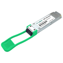
C-light QSFP28 video
At the hostboard side, Tx_fault and Rx_loss are pulled up to 3.3V power supply: at the optical module side, TX﹣disable is also pulled to the 3.3V power supply on the module through resistance. The principle of selecting pull-up resistance is that the maximum value of pull-up resistance shall ensure that the precharge voltage reaches 80% of the ideal charging voltage at the gold finger connection within a few MS; the minimum value shall ensure that the leakage current of the pin of the device at the high and low levels is not too large, and the gap between the pin and the pin of the device shall not be too large. The pull-up resistance recommended by MSA is 4.7-10kΩ.


 Your current position: