Traditional data center is mainly based on 10G network architecture. In order to adapt to AI, deep learning and large number scale deployment of computing and other businesses, the next generation data center architecture is moving to 25G / 100G network architecture evolution. It has been seen that Internet giants such as bat have realized scale deployment in China. Building a 25G / 100G data center requires a large number of 100G optical modules, which account for a relatively high proportion of the cost of network construction. What are the 100G optical module standards, and how do we choose them? Today, we will simply sort out the 100G optical module standards and packaging formats of the data center.
I. 100G optical module Standard Organization
Before sharing the optical module standards, first understand the standardization organization of the optical module. For the definition of optical modules it's mainly two key organizations: IEEE and MSA (multi source Agreement, the two are complementary and learn from each other. Possibly everyone knows IEEE is the Institute of electronic and electrical engineers, and 802.3 is a working group under IEEE. Many 10G, 40G, 100G, 400G optical module standards are proposed by IEEE802.3 working group.
MSA is a multi vendor specification. Compared with IEEE, it is a non-governmental organization form. Different MSA protocols will be formed for different optical module standards, which can be understood as the behavior of enterprise alliance in the industry. MSA not only defines the structure package of optical module (including overall dimension, electrical connector, pin distribution, etc.), but also defines electrical interface and optical interface, so as to form a complete optical module standard. A long time ago, the optical module industry chain was in a mess. Each manufacturer had its own structure package. The developed optical modules were large and small, and the interfaces were also various. To solve this problem, MSA multi-source Association is founded. All manufacturers follow the standard proposed by MSA to unify the structure packaging and relevant interfaces of optical modules, just like the standardization of mobile phone charging ports. For 100G, the standards defined by MSA include 100G PSM MSA, 100G CWDM4 MSA and 100g lambda MSA.
II. 100G optical module standard
In order to meet the 100G interconnection scenarios with different distances, the 100G standard defined by IEEE and MSA exceeds ten, but the main one is the following six standards.

In addition to the 100GBase series standards proposed by IEEE, why do MSA also propose PSM4 and CWDM standards? 100GBase-SR4 and 100GBase-LR4 are the most commonly used 100G interface specifications defined by IEEE. However, for large-scale data center internal interconnection scenarios, the distance supported by 100GBase-SR is too short to meet all interconnection requirements, and the cost of 100GBase-LR4 is too high. Therefore, MSA brings medium distance interconnection solutions to the market. PSM4 and CWDM are the products of this revolution. Of course, the capability of 100GBase-LR4 completely covers CWDM, but in the scenario of 2km transmission, the cost of CWDM scheme is lower, more competitive. The following figure is the schematic diagram of 100GBase-LR4 and 100G CWDM

LR4 and CWDM4 are similar in principle. They all divide and multiplex 4 parallel 25G channels into a 100G optical fiber link through optical MUX and demux. But there are several differences:
1. Optical MUX / demux devices used in LR4 are more expensive
CWDM defines a CWDM interval of 20 mm, because the wavelength temperature drift characteristic of the laser is about 0.08mm / ° C and within the working range of 70 ° C it's about 5.6m, and the channel itself should also be reserved some barriers.
Channel 1: 1264.5 ~1277.5nm
Channel 2: 1284.5~1297.5nm
channel 3: 1304.5~1317.5nm
channel 4: 1324.5~1337.5nm
LR4 defines a LAN-WDM interval of 4.5mm.
Channel 1: 1294.53~1296.59nm
channel 2: 1299.02~1301.09nm
Channel 3: 1303.54~1305.63nm
Channel 4: 1308.09~1310.19nm
The larger the channel spacing is, the lower the requirements for optical MUX / DEMUX devices are, and the cost can be saved.
2. LR4 uses more expensive lasers and consumes more power
CWDM uses DML (direct modulated laser), while LR4 uses EML (electronic absorption modulated laser).
DML is a single laser, and EML is two devices, one is DML, the other is EAM modulator, which is called EML together. The principle of DML is to modulate the signal by modulating the injection current of the laser. Because the injection current will change the refractive index of the active region of the laser, resulting in wavelength drift (chirp) and resulting in dispersion, it is very difficult to modulate the high-speed signal, and the transmission is not far enough. 10km is not enough for DML, only for EML.
Note: chirp refers to the signal whose frequency changes (increases or decreases) with time. This kind of signal listens like the chirp of birds.
3. Additional tec (thermo electric cooler) is required for LR4
The distance between adjacent channels of LR4 is only 4.5mm, so the laser needs to be placed on Tec to control temperature. The TEC driver chip needs to be placed on the circuit, and the laser needs to be integrated into the TEC material. In this way, the cost of LR4 is increased compared with CWDM.
Based on the above three points, the optical module cost of 100base-lr4 standard is higher, so The 100G CWDM standard MSA proposed well complements the empty space caused by the high cost of 100GBase-LR4 within 2km.
In addition to CWDM, PSM4 is also a medium distance transmission scheme, so what are the advantages and disadvantages of PSM4 compared with CWDM? The 100G PSM specification defines 8 single-mode optical fibers (4 transmitting and 4 receiving) point to point 100Gbps links, each channel is sent at 25G bps. four
Independent channels of the same wavelength is used for each signal direction. Therefore, the two transceivers usually communicate through the 8-fiber MP / MPO single-mode jumper. The transmission distance of PSM4 is up to 500m.
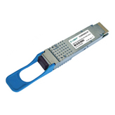
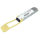
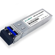
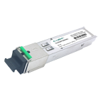
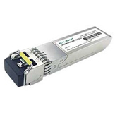
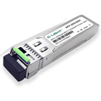
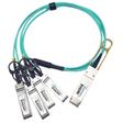
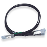
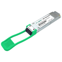
C-light QSFP28 - Quad small form factor pluggable transceivers, Data rates up to 100Gb/s and 112Gb/s. Distance 100m SR, 2km/10km CWDM4, 10km LR4, 20km LR4, 40km ER options. 850nm MPO, 830/850/870/890nm swdm4, 1310nm, and 1550nm options. Range of passive DAC cables and AOC cables are available from C-LIGHT list for use in IDC and enterprise networks.


 Your current position: